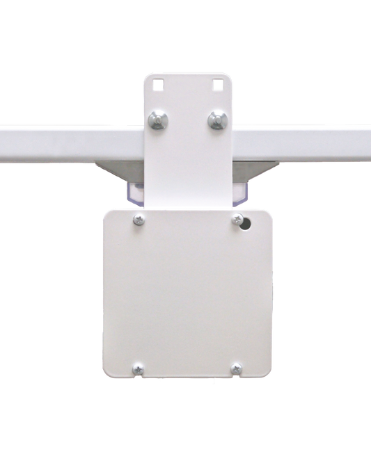
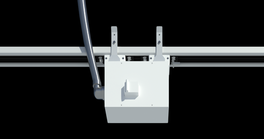
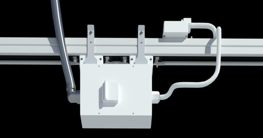
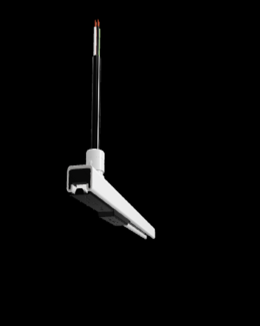
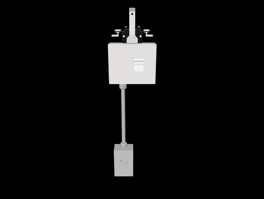
Configure a 40A Row
Build a 40A row, add feeds and PowerDrops, see the system in 3D, and review the BOM and pricing.
 Open the 40A Configurator →
USA TrackBusway manufactures two open-channel systems: 40A Track Busway (T40) and 225A Track Busway (T225). Use this Buyer’s Guide to choose the system that fits your project, then plan FEEDs and compatible POWER Plug-Ins for your overhead power layout.
Expand capacity with additional separately fed runs or electrically isolated sections. Each section retains its own current rating; adding feeds does not increase the rating of an individual section.
Planning your layout? Follow our Design Your Track Busway System guide.
Explore a layout in 3D, or follow the selection steps below to choose your system, FEEDs and POWER Plug-Ins.
Build a 40A row, add feeds and PowerDrops, see the system in 3D, and review the BOM and pricing.
Open the 40A Configurator →Choose run length, PowerDrops, feeds and splitter options. Explore the layout in 3D and review component pricing.
 Open the 225A Configurator →

For use with Track Busway systems rated up to 40A per phase. Single-phase layouts offer two 20A or 40A circuits per deck, or up to four circuits when stacked. Three-phase layouts offer 20A or 40A per phase.

Up to 225A per phase, per feed. Separately fed sections do not increase any section’s rating. Options include 200% Neutral (N2), Isolated Ground (IG), or both (N2IG). Match components to the project’s neutral and grounding requirements.
Modular busway lengths and all components needed to build a continuous RUN (lengths, mechanical joiners, electrical joiner inserts, hangers, cable kits, closure strip).
225A Track Busway is the higher-capacity USA TrackBusway system for heavier overhead power distribution applications.
This section includes the main 225A run components used to build the busway path: lengths, joiners, and suspension hangers. T225 end feeds and monitoring choices are in Step 2.
Your selected system determines the compatible feed family: T40 feeds for 40A Track Busway or T225 end feeds for 225A Track Busway. Plan feed quantity and locations around the layout, calculated loads and project requirements.
Review the T40 feed options below, or jump to T225 end feeds and monitoring choices. Coordinate separately fed sections and protection with the electrical design; additional feeds do not increase a section’s rating.
For the 225A system, use a matching 225A end feed. T225 end feeds and T40 feeds belong to different system families and are not interchangeable.
StandardStandard neutral configuration
200% Neutral (N2)Additional neutral capacity
Isolated Ground (IG)Separate isolated-ground path
200% Neutral + IG (N2IG)Both conductor options
Each feed type is available with No Power Monitoring or Critical Power Monitoring. Match the feed, busway lengths and electrical joiners to the selected conductor configuration, then choose compatible tap-offs.

T225 end feed without a meter or display. Select Standard, N2, IG or N2IG on the product page.
View T225 feeds without monitoring →
T225 end feed with Schneider power monitoring. Available with Standard, N2, IG or N2IG; confirm the meter and communications for the project.
View T225 feeds with monitoring →Explore critical power monitoringCompare neutral and grounding options

40A Tap off POWER Plug-Ins bring 120V, 208V, 240V, or 480V down to equipment, receptacles, or machines — anywhere along the run.

225A tap off POWER Plug-Ins bring 120V, 208V, 240V, or 480V down to equipment, receptacles, or machines — anywhere along the run.
Deliver power anywhere along the busway—no rewiring required.
1-pole tap-off units deliver 120V line-to-neutral power from the 40A Track Busway system. Use these for standard receptacles, cord drops, outlet boxes, and light-duty equipment connections.
2-pole tap-off units draw power line-to-line for 208V or 240V loads. Use these for equipment that requires higher single-phase voltage from the overhead Track Busway run.
3-pole tap-off units provide three-phase power from double-deck Track Busway runs. Use these for motors, machinery, and equipment that requires balanced three-phase power overhead.
T225 POWER Tap-Off Units deliver localized 120V, 208V, 240V, 480V, or three-phase power from the 225A Track Busway system, allowing equipment connections to be positioned where the layout requires them.
T225 1-pole tap-off units provide 120V line-to-neutral power from the 225A Track Busway system. These units support higher-capacity projects while still allowing localized plug-in access along the run.
T225 2-pole tap-off units provide 208V, 240V, or 480V line-to-line power from the 225A Track Busway system. Use these for heavier single-phase equipment loads that need power positioned overhead.
T225 3-pole tap-off units provide three-phase power from the 225A Track Busway system. These are intended for higher-capacity equipment, machinery, and project layouts that require three-phase distribution along the run.
Some projects call out “dedicated ground,” isolated ground (IG), equipment grounding requirements, 200% neutral (N2), or 200% neutral + isolated ground (N2IG). These requirements are project-specific and must be coordinated with the selected 225A / T225 configuration, project drawings, load calculations, voltage system, and electrical engineer requirements.
Review grounding and conductor configuration guidance.