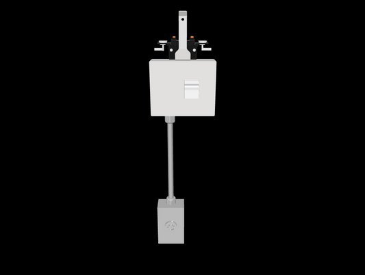
Standard Equipment Ground
Standard equipment grounding through the enclosure and housing ground, where listed for the selected interface and build.
| System | T225 Track Busway (up to 225A per phase) |
|---|---|
| Phase | Three-phase power distribution |
| Voltage | 208V, 208Δ, 480V, 480Δ |
| Amperage | 20A / 30A / 60A |
| Wiring Configuration | 3-pole (with and without neutral) |
| NEMA / IEC Receptacle Type | L15-20R, L15-30R, L16-20R, L16-30R, L21-20R, L21-30R, 15-60R, 560R9W, 560R7W |
Watch how this product installs, connects, or configures with the Track Busway system
For additional installation scenarios, configuration examples, and system overviews, visit the Track Busway Video Library →
Drag or use arrow keys to rotate. Scroll or pinch to zoom.
USA TrackBusway
Catalogue # (SKU): Select configuration
Select a configuration to view its exact price and data sheet.
An IG option label does not establish internal bonding, conductor routing or complete assembly suitability.
Compare receptacle options Understand critical power monitoring (CPM)
Couldn't load pickup availability
View Complete Product Family Technical Guide (PDF)
A verified technical sheet is not yet available for this selection. Request a configuration-specific sheet and include the details below.
Copy the details, then paste them into Message on the contact page. They are not transferred automatically.
Revision 1 · August 1, 2026 · 3 sheets
One representative coordination type: T225-C-10-DCXX-L2120-G. Confirm the selected configuration for your project.
Looking for more technical assets?
These protected 3-pole drop cord units plug into the USA TrackBusway T225 system to deliver 3-phase branch power directly from the overhead busway run. They are designed for compatible NEMA receptacle configurations up to 60A and are commonly used where industrial equipment, critical power loads, or higher-capacity plug-in power access is required.
The PT225 family includes cETLus Listed tap-off configurations for the T225 continuous plug-in busway system, evaluated by Intertek to UL 857 and CSA C22.2 No. 27.
Intertek Control No. 5011082. Intertek Report No. 106508638CRT-001.
Depending on the selected configuration, C (Compact) enclosure units support up to two drop cords, while S (Standard) enclosure units support up to three drop cords. Total connected drop-cord load cannot exceed 60A per phase across the tap-off unit. Compact and standard enclosure options are available based on receptacle count, breaker type, and whether critical power monitoring features are selected.
Integrated MCB, MCCB, or CubeFuse overcurrent protection is available by configuration. Optional monitoring configurations may include Schneider Electric PM5000-series or HDPM6000-based monitoring for projects requiring metering, alarms, or power visibility. Isolated ground receptacles are available when specified; otherwise, units are supplied with standard equipment grounding through the enclosure and housing ground.
Units ship factory assembled and ready for installation, with secure attachment to the Track Busway slot using one or two mounting tabs depending on enclosure size.


Choose 208V three-phase with neutral, 208V three-phase without neutral, 480V three-phase with neutral, or 480V three-phase without neutral. A three-pole branch uses three line conductors; neutral-bearing arrangements add a neutral conductor.
Documented standard-interface branch selections include 20A, 30A. Standard and isolated grounding choices apply only where listed for the selected interface and build. Device pole/wire counts and nominal device ratings are distinct from breaker pole counts and selected supply voltage.
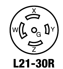
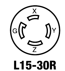
Interface examples only; not finished tap-off assemblies or a supplier or assembly-rating claim.
| Interface | Nominal device rating | Selected supply application | Style |
|---|---|---|---|
| L15-20R | 20A; 250V AC, three-phase | 208V three-phase without neutral | Locking |
| L15-30R | 30A; 250V AC, three-phase | 208V three-phase without neutral | Locking |
| L16-20R | 20A; 480V AC, three-phase | 480V three-phase without neutral | Locking |
| L16-30R | 30A; 480V AC, three-phase | 480V three-phase without neutral | Locking |
| L21-20R | 20A; 120/208V AC, three-phase wye | 208V three-phase with neutral | Locking |
| L21-30R | 30A; 120/208V AC, three-phase wye | 208V three-phase with neutral | Locking |
| L22-20R | 20A; 277/480V AC, three-phase wye | 480V three-phase with neutral | Locking |
| L22-30R | 30A; 277/480V AC, three-phase wye | 480V three-phase with neutral | Locking |
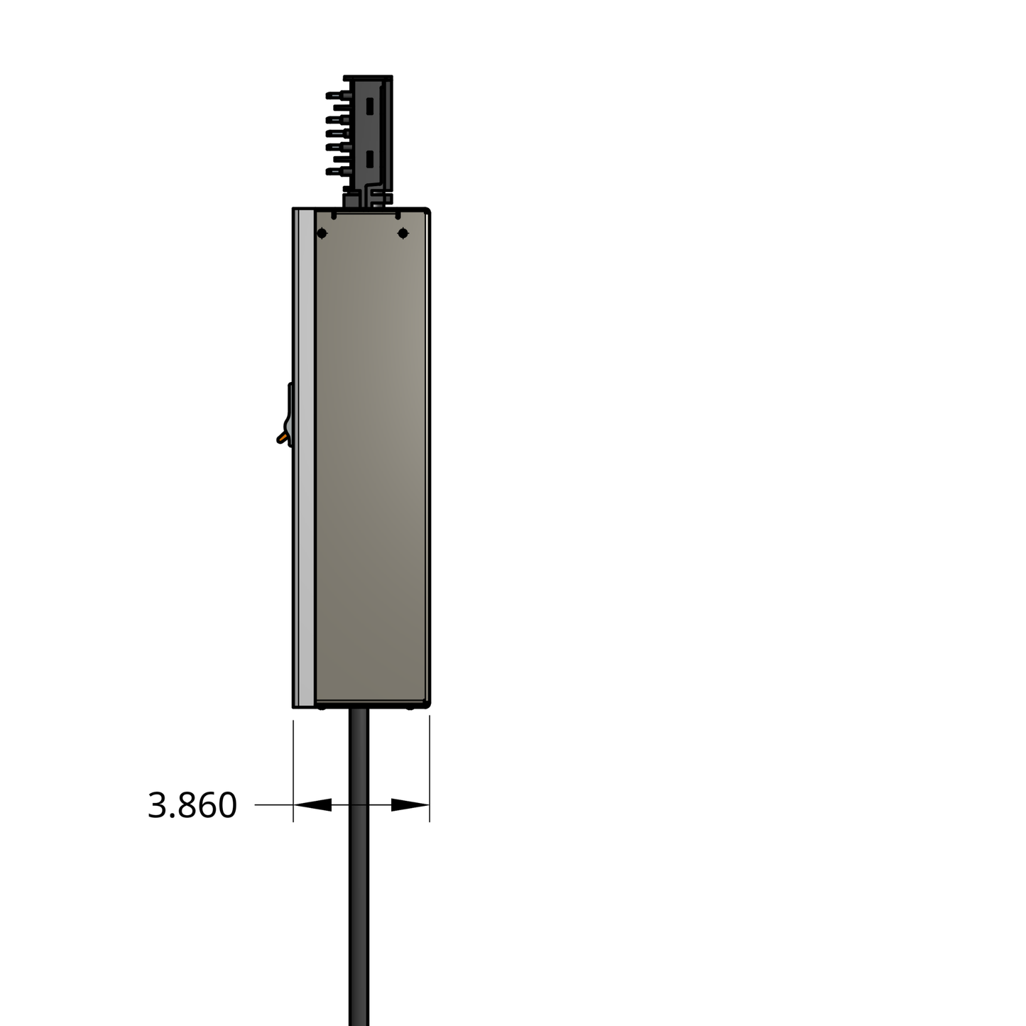
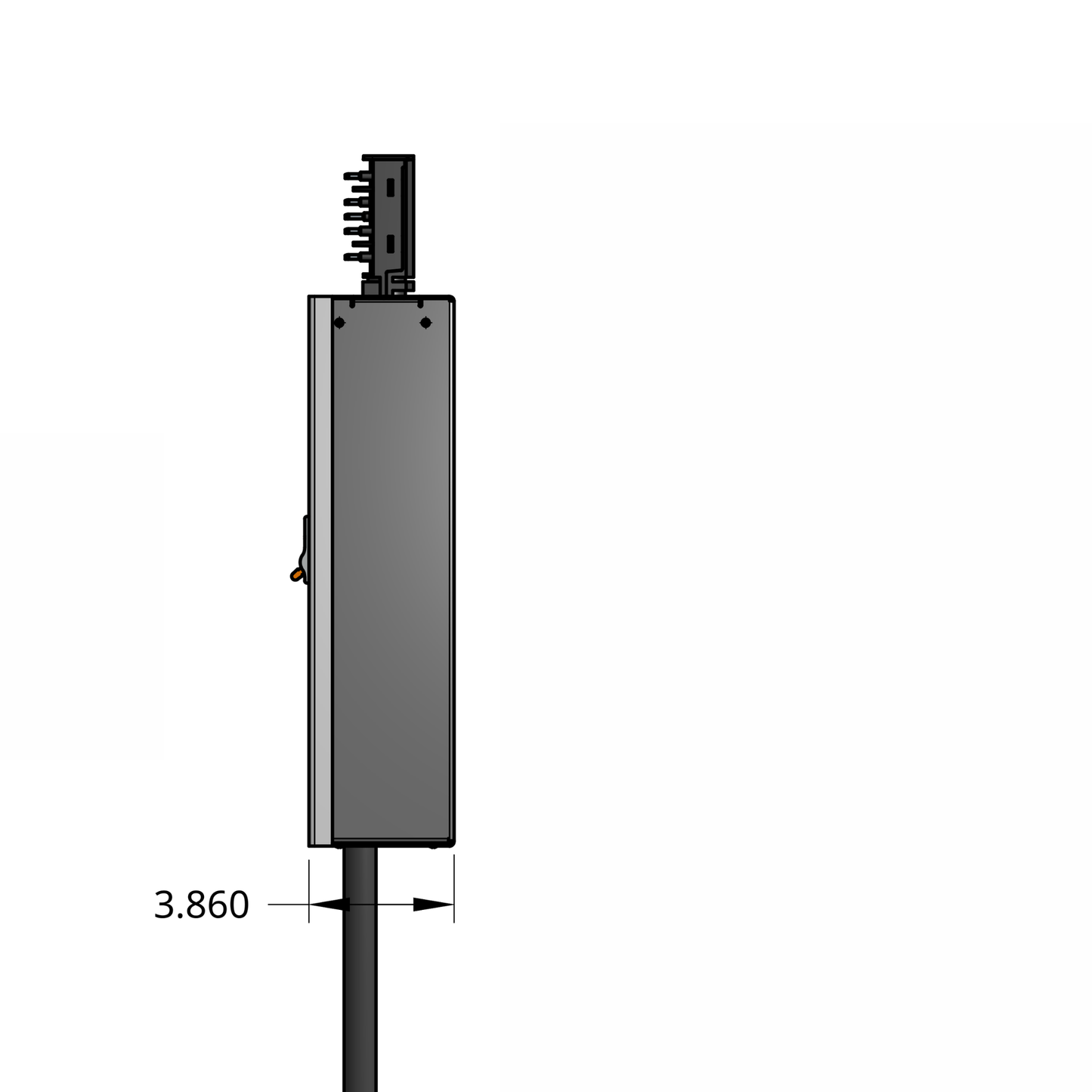
Documented body references are compact C-10, 9.420 inches wide by 14.120 inches high by 3.860 inches deep, and standard S-10, 13.280 inches wide by 14.620 inches high by 3.860 inches deep. These are body dimensions, not overall dimensions including projecting fittings or required installation clearances. The exact configuration determines enclosure applicability. Flexible cords are outside the body envelope; finished cord length is specified per order.
Listed configurations include compact single-output and standard two-output cord builds where supported. Each selected sheet identifies the cord quantity and corresponding branch protection.
PM5000 and HDPM6000 monitoring options and 60A industrial-interface selections are listed for applicable configurations. Their actual finished assembly, monitoring fit and protection layout require the corresponding factory documentation; the standard-interface drawings do not establish those builds.
Select the power, electrical and build options on this product page to see the Selected Technical Configuration and its matching one-page sheet when available. Configurations awaiting confirmation use Request Configuration-Specific Data Sheet. The family guide explains selection scope; a representative body illustration must not be treated as an exact finished configuration.
Standard equipment grounding through the enclosure and housing ground, where listed for the selected interface and build.
An isolated-ground conductor arrangement where supported by the selected receptacle, build and project design. An IG option is not a substitute for equipment ground.
Compare receptacle and grounding options
This factory-assembled T225 drop cord tap-off unit can be specified with standard equipment grounding or isolated ground (IG) receptacle options where supported by the selected receptacle and build configuration. “Dedicated ground” language must be confirmed against the project drawings as isolated ground, equipment grounding, or another project-specific grounding requirement.
For N2 or N2IG projects, coordinate the tap-off with the matching 225A / T225 busway and feed configuration.
Review grounding and conductor configuration guidance.