
USA TrackBusway · Safety & listings
Track Busway.
Listed to UL 857.
Flexible power. Protected conductors. Verified listings.
Our T40 three-phase and 225A systems are listed to UL 857 Busway Standards. Explore the construction behind the connection—and the independent records behind your specification.
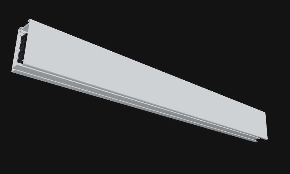
Inside the system
An open slot. Protected conductors.
Finger-safe construction helps prevent accidental contact with energized copper. The continuous insulator shields the conductors from finger contact through the plug-in slot when the system is correctly assembled and installed. Compatible tap-offs make the intended electrical connection inside that protected channel.

Conductor detail shown. Deck and phase arrangements vary by the selected configuration.
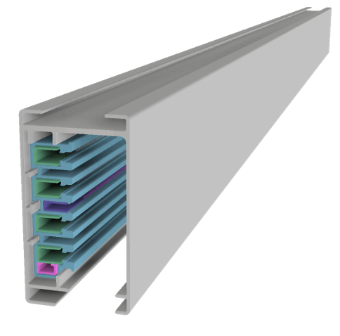
Section view for illustration. Installed ends and joints use the required closures and fittings.
Insulate the conductors
The continuous insulating structure separates the copper conductors and helps restrict accidental access.
Maintain the ground path
Bonded metal housings and compatible fittings form part of the system’s equipment-grounding path.
Use the matching tap-off
Match the busway family, equipment connection and circuit protection. Each tap-off has its own marked rating.
Finger-safe construction applies to normal access through the assembled slot. Follow the product instructions for installation and service; keep tools and foreign objects out of the channel. Review installation guidance
The evidence behind the system
Two systems. Direct access to the listing records.
UL 857 is the busway safety standard. Intertek is the listing organization. The records below identify the evaluated product families and the ETL Listed mark. Canadian records reference CSA C22.2 No. 27.
40A three-phase steel Track Busway
Listed to UL 857 Busway Standards
Continuous plug-in busway and associated fittings, including the M40 family.
Records are filed under our parent company’s legal name.
Match your T40 configuration
Match the selected busway, feed and tap-off models to the applicable 40A listing documents. A proposed three-phase receptacle build must match its exact connector, protective device and finished assembly; amperage alone does not establish coverage.
Get help matching your T40 part number225A continuous plug-in busway
Listed to UL 857 Busway Standards
Applicable T225 busway, JK225 joiners, EF225 end feeds and PT225 tap-off configurations.
Control No. 5011082 · Report No. 106508638CRT-001
For the specification
Match the listing to the complete assembly.
T40 or T225: start with the documented configuration
Use these family references to begin selection. Confirm the exact catalog numbers, connected assembly and marked ratings for your project.
T40 · Steel Track Busway
- System & run enclosure
- The length sheets document a 40A option, up to 600V maximum, in steel housing: single-phase, 3-pole or double-deck three-phase, 4-pole. Match the feed and deck wiring.
- Tap-off connection & enclosure
- Choose a factory outlet box with an integral receptacle or a PowerDrop assembly with a cord-end connector. The documented 120V outlet box has a 15A, 1-pole breaker in current online models; three-phase PowerDrops use matched 20A or 30A, 3-pole protection. Select the enclosure, supply and connection from the exact device sheet.
- Listing scope
- The T40 listing record covers M40-family three-phase busway and specified fittings under Architectural busSTRUT Corp., our parent company. Match the selected model and finished build; a family name alone does not establish coverage.
T225 · Aluminum Track Busway
- System & run enclosure
- The length data sheet specifies 225A per phase, up to 600V AC, three-phase plus neutral, 4-pole construction in an aluminum housing.
- Tap-off connection & enclosure
- PT225 options include standard-size and compact enclosures, with outlet-box or drop-cord connections. Match the protective device, receptacle or connector, monitoring and marked-unit ratings. Use the detailed model-scope table below for the documented options.
- Listing scope
- Standard (S) and 200% Neutral (N2) T225 lengths and end-feed configurations appear in the public listing. Obtain model-specific listing and rating evidence for IG/N2IG. The Standard/N2 busway SCCR statement below must not be extended to IG/N2IG or assumed for every tap-off.
- Project supply and load: What voltage, phase, conductor arrangement and calculated capacity are required?
- Equipment connection: Which tap-off, enclosure, receptacle or cord connection and circuit protection are required?
- Complete-assembly match: Do every selected component and the complete assembly meet the applicable listing and marked voltage, current and short-circuit ratings?
Standard and 200% Neutral (N2) configurations are included in the public T225 listing. Match the model pattern, selected components and finished-assembly documentation.
Standard and 200% Neutral (N2) T225 busway configurations have a 22 kA short-circuit current rating (SCCR).
T225 model scope and selected-build ratings
| Product | Listed scope |
|---|---|
| T225 lengths | T225-4-600; length codes 01–10; N/B/W finish; Standard (S) or 200% Neutral (N2). |
| EF225 end feeds | Standard (S) or N2; standard/reverse orientation; NPM, EPM or SPM monitoring configurations. Confirm the retail monitoring SKU against the listed feed model. |
| JK225 joiners | JK225-E electrical and JK225-NE non-electrical joiners; optional 4-600 suffix. |
| PT225 tap-offs | Standard-size (S) and compact (C) enclosures; drop cord (DC) and outlet box (OB); NPM, EPM, SPMH and SPMP monitoring options. Match the receptacle, protective device, amperage, voltage and monitoring to the controlled build and nameplate. |
| Hangers and end caps | Components used in the listed 225A system. The report identifies these as unlisted components within the evaluated construction, not individually ETL Listed products. |
For IG and N2IG busway/feed configurations, request model-specific listing and ratings documentation for the selected assembly before specifying. An isolated-ground receptacle is a separate configuration question from an IG busway run; its device and complete grounding path must match the selected assembly.
Ratings follow the complete assembly. The lowest-rated installed component governs. A receptacle rating, breaker interrupting rating, CAD drawing or product-family name does not establish the finished tap-off rating. Request the configuration-specific listing and ratings information for project submittals.
T225 Compliance & Submittal Library
Find the documents for Standard and 200% Neutral (N2) T225 configurations. Both busway configurations have a 22 kA short-circuit current rating (SCCR).
Match each end feed, joiner and tap-off to its model-specific documentation and marked ratings.
- Listing & model coverage: Intertek records and model matrix
- Product documents: Busway, feed, joiner and tap-off data sheets
- Neutral & grounding: Configuration guidance
- Installation & inspection: 225A installation manual — 00001, Rev 1, August 1, 2026 · USA TrackBusway
- Project submittals: T225 Submittal Checklist — T225-SC-01, Rev 1, October 9, 2026 · USA TrackBusway
- Supports: H225-S hanger data sheet — T225-CS-02, Rev 3, September 27, 2026 · USA TrackBusway
- Replacement parts, warranty and support
Temperature-rise evaluation
Representative T225 construction passed temperature-rise evaluation. The documented test program included a 225A busway specimen, a circuit-breaker tap-off tested at 48A, and a fused tap-off tested at 60A. These currents describe the tested specimens; select each finished assembly by its marked rating and configuration. Contact USA TrackBusway for applicable test documentation.
Protection and coordination
Include system voltage, available fault current, assembly SCCR, protective-device models, interrupting ratings and applicable settings in your submittal. The project electrical engineer should review coordination using the applicable curves or tested-combination information.
Supports and seismic requirements
For indoor, horizontal runs, use H225-S hangers with the specified 3/8-inch–16 threaded-rod connection. Install two approved hangers per 10-foot section, place a hanger within 12 inches of each continuous-run end, and keep adjacent supports no more than 10 feet apart. Coordinate structural attachments and any required seismic bracing with the project’s structural design.
From specification to submittal
Make the approval package easy to review.
Start with the listing record, then add the documents for the system and equipment connections you are actually specifying.
- 01Identify the products
Complete part numbers, labels, cut sheets and the applicable listing record.
- 02Define the electrical arrangement
Supply voltage, phase, deck arrangement, wiring diagrams, protection and available fault current.
- 03Coordinate grounding & neutral
Equipment grounding, bonding and any specified isolated-ground or neutral configuration.
- 04Document the installation
Supports, clearances, environment, current instructions and approved project drawings.
T225 evidence cross-reference
Use the model-scope table above with the documents below. Record document number, revision and selected catalog number in your submittal.
- Busway/feed/joints: Compare the length, standard unmetered feed and joiner datasheets with the listing. Obtain selected-build evidence for monitored feeds and IG/N2IG.
- Tap-offs: Select the exact configuration through the technical library and include its datasheet, protective-device details and nameplate ratings. A family guide alone does not identify the finished assembly.
- Installation/acceptance: Include the T225 manual, pre-energization checklist and approved support details. Assign inspection, testing and handover responsibilities in the submittal checklist.
The manual’s 22 kA SCCR statement applies to chassis-ground-only configurations. Verify the marked rating and applicable evidence for the selected assembly; do not extend that statement to IG/N2IG. Request any project-required coordination, temperature-rise or seismic evidence for the exact configuration.
Listing scope and project approval
Confirm busway, feeds, tap-offs, accessories and protective-device combinations against the chosen family’s listing documents. The product listing covers its specified configurations; the installation is reviewed against the applicable code and approved drawings.
NEC Article 368 addresses busways. The electrical engineer defines the design and protection, the contractor follows current instructions and approved documents, and the authority having jurisdiction (AHJ) determines installation approval under locally adopted requirements.
Installation & reconfiguration
Use the right procedure for the selected device.
Qualified personnel must follow the product-specific instructions, approved project documents, applicable electrical and workplace-safety requirements, site procedures and AHJ direction. This overview is not an energized-work procedure.
View installation guidanceWhere the product instructions permit handling a breakered tap-off with the busway energized, keep its integral breaker OFF throughout installation, removal or relocation.
Switch ON only after the tap-off is fully installed and secured. Lighting and other non-breakered devices follow their own instructions.
