
225A Track Busway · T225
Critical Power Monitoring
See where your power is going.
Choose monitoring at the feed, at selected tap-offs, or both. Match the measurement points to the busway runs and equipment connections you want to understand.
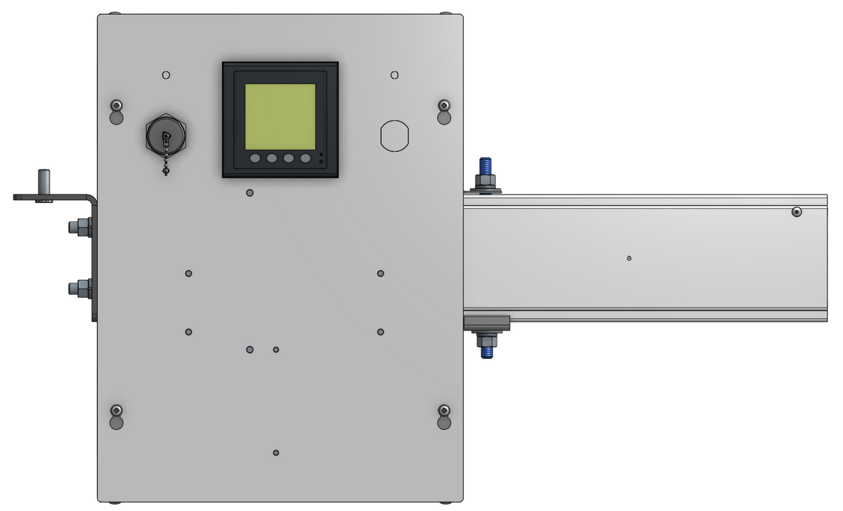
Choose what you want to see
Start with the measurement point. Feed readings and individual connection readings answer different questions.
Monitor the run
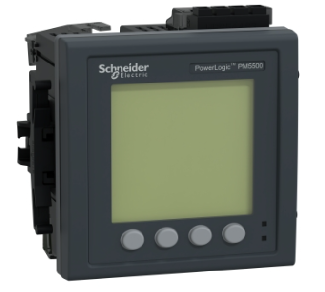
See the load on each phase and across the busway run. Feed monitoring does not show individual tap-off loads.
Monitor selected connections
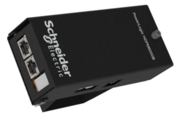
Add metering at selected tap-offs to see individual equipment connections. Available measurements depend on the specified assembly.
Selected T225 tap-offs offer PM5000-series or HDPM6000 monitoring. Select the monitored build with its voltage, breaker rating and receptacle layout. Explore T225 power tap-off units.
Know what your readings include
The selected Schneider hardware can provide current, voltage, power, energy and power-factor data. Confirm the exact measurements, alarms and retained history for your meter and receiving software.
Power-quality limits: PM5560 does not provide sag/swell detection or waveform capture. Specify advanced power-quality recording separately.
Downstream equipment: Rack-PDU inlet, branch and outlet telemetry requires separately selected rack-PDU or other downstream monitoring equipment.
Connect to your monitoring software
Bring readings into your building or power-monitoring software so your team can review the specified measurement points together.
Confirm the meter, supported protocol and receiving-system integration requirements for your project. Native protocol support alone does not guarantee a working dashboard or alarm delivery; any required gateways and software licenses must be included in the agreed scope.
Local display, optional HMI and networked web-interface availability depend on the selected Schneider hardware.
Technical details for your project
Documentation reviewed October 21, 2026. Manufacturer-documented capabilities must be checked against the supplied configuration.
Measurements and monitoring points
Choose the measurement point first, then the meter and integration:
- Feed: Schneider metering is a regular T225 end-feed option. The meter measures each phase of the run. Use it to review run loading and phase balance. Feed readings alone do not identify the load on every downstream tap-off.
- Tap-offs and PowerDrops: metering is available at selected T225 tap-offs. A two-cord PowerDrop can also provide separate measurements for each cord output as a project-specific configuration.
- Rack PDU: busway metering measures the specified busway connection. Rack-PDU inlet, branch and outlet telemetry depends on the separately selected rack PDU or other downstream monitoring equipment.
The selected Schneider hardware can provide current, voltage, power, energy and power-factor data. PM5560 supports measurement on 208 V and 415 V systems, along with demand readings and configurable threshold alarms; confirm the complete T225 assembly, CTs and wiring for the project. Confirm the exact measurements, alarm thresholds, reporting intervals and retained history for the selected meter and receiving software.
Advanced power-quality recording, such as sag/swell detection or waveform capture, must be specified separately; PM5560 does not provide those features.
Schneider PowerLogic PM5000-series meters are available in monitored T225 feed assemblies and selected individual T225 tap-off configurations. Use feed metering for visibility across a run, and monitored tap-offs for the equipment connections you want to measure separately.
The T225 1-pole outlet-box selector, for example, offers Schneider PM5000 monitoring under Connections & monitoring.
Schneider HDPM6000 provides modular, distributed monitoring with a head unit and metering modules at selected points. Individual T225 power-tap product pages also offer HDPM6000 build options.
Select the monitoring option with the tap-off’s voltage, breaker rating and receptacle layout. Explore T225 power tap-off units.
PM5560: model, protocols and firmware
PM5560 (METSEPM5560): native Modbus TCP/IP over Ethernet and Modbus RTU/ASCII over RS-485.
Schneider introduced BACnet/IP support for PM5560 in firmware 2.3.0; verify the supplied firmware, protocol settings and receiving-system support.
Other PM5000 models do not necessarily offer the same interfaces.
A separate protocol converter is not required for the PM5560’s native Modbus TCP/IP connection, but the receiving software still needs a compatible driver and agreed point mapping.
Not necessarily. PM5560 itself is an integrated-display, panel-mount meter, but Schneider’s PM5000 family also includes no-display and remote-display variants. In the HDPM6000 platform, the HMI/display is optional.
HDPM6000: modules, head unit and firmware
HDPM6000: selected HDPM6000B busway modules connect to a head unit over the dedicated HDPM bus using CAT6 cable, not the facility Ethernet network.
The head unit supports Modbus TCP/IP over Ethernet, Modbus RTU over RS-485, and BACnet/IP and SNMP v2 over Ethernet.
Confirm the exact head-unit/module combination and firmware bundle.
Schneider requires compatible bundle versions across the head unit and connected system components; do not assume an arbitrary firmware combination is supported.
Integration requirements: BMS, EPMS and DCIM
Documentation reviewed October 21, 2026. These are manufacturer-documented capabilities, not a certification of every installed configuration.
USA TrackBusway has confirmed successful BMS integration with Schneider power metering.
For each BMS, EPMS or DCIM project, have the integrator confirm the software/version, device driver, register or object map, measurements, polling and alarm workflow.
Document any required gateway or protocol converter and software, device or point licenses in the project scope; do not assume they are included with the meter.
Native protocol support does not guarantee a ready-made dashboard, automatic discovery or end-to-end alarm delivery.
Use an appropriately secured facility network and follow Schneider’s cybersecurity guidance.
Specify and commission the complete measurement path
- Mark the feeds, selected tap-offs and downstream rack-PDU points to be monitored on the drawings.
- Confirm the factory assembly, meter or HDPM module, CT type and ratio, measurement-voltage limits, display and channel-to-circuit mapping.
- Agree the network interface, addresses, point map, units, scaling, polling interval, time synchronisation and history requirements with the integrator.
- Define alarm thresholds, delays, priorities, recipients and the response to a lost communications connection.
- Before acceptance, verify phase association and CT polarity, compare readings with an appropriate reference, and test point mapping and alarms in the receiving software. Record the final configuration and handover responsibilities.
Request the selected monitored-feed sheet and configuration-specific tap-off documentation as part of the project submittal.
Project example: two independently supplied 415 V runs
An anonymous data-center project specified two 46.5-foot T225 runs, each with a Schneider PowerLogic PM5560 meter in the standard end feed. The meter measures each phase at the feed for visibility across that run.
The runs are independently supplied. Each supply has upstream three-pole circuit-breaker protection outside the end feed; tap-offs provide overcurrent protection at their equipment connections. The metering function is the same whether a project uses one supply path or independent A/B paths. Power-source independence is an electrical-design feature, separate from the meter’s measurement function.
Each separately fed T225 run remains rated up to 225A per phase. Match the actual rack loads, protection and required operating conditions to the approved project design. Where individual equipment-connection readings are needed, selected T225 tap-offs can be specified with monitoring. A two-cord PowerDrop can also be configured with separate monitoring of each cord output as a project-specific build.
Choose the monitored build in the T225 product selector or explore the T225 power tap-off range.
Dated Schneider documentation and source links
Documentation reviewed October 21, 2026. These are manufacturer-documented capabilities, not a certification of every installed configuration.
Manufacturer documentation reviewed:
- PM5500 / PM5600 / PM5700 User Manual — HRB1684301-18 (December 2025)
- PM5560 / PM5563 firmware 2.3.0 addendum — 7EN12-0294-00 (March 2016)
- HDPM6000 Head Unit Installation Guide — Z208128-0L (April 2026)
- HDPM6000 Protocol Guide — ZL0192-0G (April 2026)
- HDPM6000B Installation Guide — Z208131-0E (May 2022)
Monitoring questions
What is critical power monitoring for Track Busway?
Critical power monitoring for Track Busway adds visibility at the monitored feed and, where specified, at selected tap-off or drop locations so facility teams can review electrical conditions more clearly.
Is there only one Schneider monitoring option?
Schneider PM5000-series and HDPM6000 options are available for T225 monitoring. Selected individual T225 tap-off units offer either option in their product configurators, alongside monitored feed assemblies.
Does every monitoring configuration include a local display screen?
Not necessarily. PM5560 itself is an integrated-display, panel-mount meter, but Schneider’s PM5000 family also includes no-display and remote-display variants. In the HDPM6000 platform, the HMI/display is optional.
How does the monitoring connect?
Schneider PM5560 connects to compatible BMS and power-monitoring software through native Modbus TCP/IP over Ethernet. USA TrackBusway has confirmed successful BMS integration with Schneider power metering. Match the selected meter or HDPM6000 hardware, network settings and measurement points to the receiving system.
Can individual T225 tap-off units include power monitoring?
Yes. Selected individual T225 power tap-off units offer Schneider PM5000-series or HDPM6000 critical power monitoring (CPM). Choose the monitored build in the product selector. Feed monitoring measures the run; monitored tap-offs add measurements at selected equipment connections. A two-cord PowerDrop can also be configured with separate monitoring of each cord output as a project-specific build. Monitoring is an order option, so select it for each point you want included.
Plan the monitoring with your project
Share the feeds and equipment connections you want to measure, the readings you need and your receiving software. We can help match the monitoring scope to your T225 layout.
