
T225 · 225A per phase
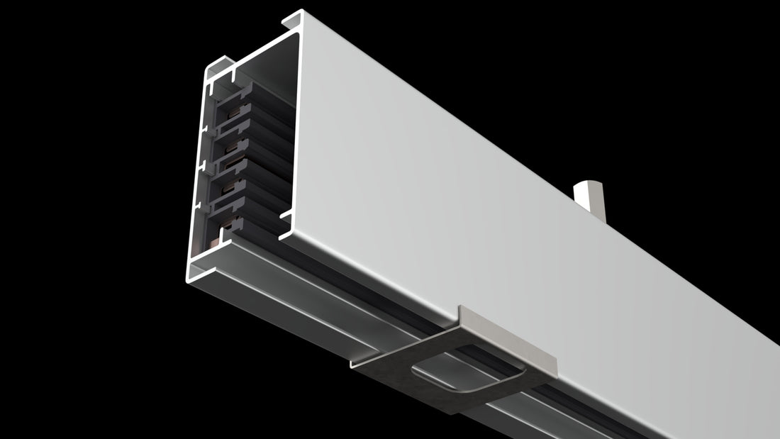
Three-phase plus neutral, with configured breakered tap-off assemblies.
Explore T225Keep power within reach as benches, instruments and workflows change with overhead, plug-in Track Busway.

Start with the available supply, equipment loads and connection requirements. Then match the busway system and tap-offs to the laboratory plan.
Three-phase plus neutral, with configured breakered tap-off assemblies.
Explore T225Compare the documented configurations and listing scope with the actual supply, project loads and each selected tap-off’s marked ratings. Laboratory size or the T225 current limit alone does not determine the choice. Match Outlet Boxes and other connections to the selected system.
| Laboratory plan | Architecture to evaluate | Check before selecting |
|---|---|---|
| Stable benches and connection points | Fixed-location plug-in busway is a valid option when its factory-positioned windows suit the planned locations. Continuous access can also serve a stable layout. | Window positions, equipment clearances and cord reach; stable benches do not require one access style. |
| Moving benches or changing outlet positions | Continuous-access track busway can support compatible tap-offs at permitted locations along the run. | Proposed positions, keep-out areas, cord routing and the documented relocation procedure. A changing layout alone does not establish suitability. |
| Instrument and circuit requirements | Evaluate either architecture against the equipment and available approved devices. | Receptacle/connector designation, branch protection, supply voltage and phase, neutral/ground configuration, simultaneous load and starting requirements in current product documents. |
Compare busway access architectures → · Review current technical documents →
Typical need: 120V single-phase receptacles
Track Busway solution: 1-pole plug-in power drops or outlet boxes
Typical need: 208V or 240V line-to-line power
Track Busway solution: 2-pole plug-in power drops or outlet boxes
Typical need: Three-phase power
Track Busway solution: Three-phase Track Busway with 3-pole / 4-wire plug-in options
Typical need: Overhead task lighting, data drops, and organized cable routing
Track Busway solution: Lighting plug-ins, data attachments, and cable-management options where applicable
For laboratory projects comparing bus duct, busduct and conduit, evaluate Track Busway as a flexible plug-in option for bench and equipment access. Include power, data and lighting needs in the layout review.
 Open T225 configurator
 Open T40 configurator
Explore connection options for benches, testing zones and shared work areas. Final selections depend on the equipment, approved system design and project requirements.
USA TrackBusway provides continuous overhead access for plug-in power drops and outlet boxes. Drops can be positioned above benches, instruments, test equipment, or future work zones, helping reduce cord clutter and keeping power accessible where the work is happening.
Laboratory systems may be configured for 120V, 208V, 240V, or three-phase power depending on the equipment, approved system design, and project requirements.
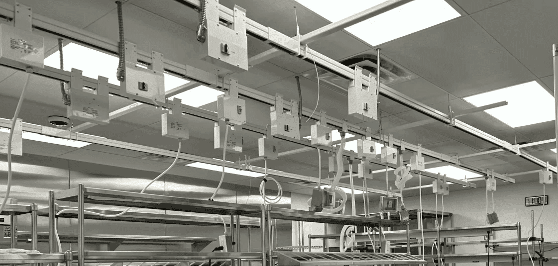
Laboratory benches and workstations often support changing equipment, users, and workflows. Track Busway allows power drops to be positioned directly above benches so power can remain accessible even as the bench layout changes. This helps laboratories avoid being locked into fixed outlet locations or floor-level power points.

Research, development, testing, and prototyping spaces often change faster than the building infrastructure around them. Track Busway creates an overhead framework for plug-in power so equipment zones can be adjusted, expanded, or reorganized without full conduit rework.

Makerspaces and shared laboratory environments benefit from power that can adapt as projects, tools, and users change. Track Busway supports flexible access to power across multiple work areas, helping teams support temporary setups, rotating equipment, and collaborative experimentation.

Laboratory infrastructure is not limited to receptacles. Track Busway can help organize power, lighting, and data support above the workspace, reducing floor-level clutter and keeping utilities closer to benches, equipment, and work zones.
USA TrackBusway is Listed to UL 857 Busway Standards for use as a busway system. Laboratory projects should be designed and installed by qualified electrical professionals in accordance with applicable codes, project requirements, and final approved drawings.
At a research laboratory, three existing USA TrackBusway tap-offs were relocated between workstations as the layout changed. The April 2024 project closeout documents the relocation. This completed project shows how an existing installation can adapt to a new workstation arrangement.
USA TrackBusway supplied a 40A overhead grid for laboratory and work areas at M.C. Dean's San Jose facility.
USA TrackBusway supplied overhead power and lighting for Shake Shack's Innovation Center in Marietta, Georgia, including 40A powered track, power drops and retractable cord reels.


Two proposed changes: move Bench B and its existing PowerDrop left, and add Bench C with one additional connection. Bench A and its PowerDrop stay in place. The same blue overhead busway remains in both layouts; proposed connection positions and added load require review.
Blue: 120V single-phase bench run
Existing PowerDrops for A and B
Same blue busway and supply
Relocate B’s PowerDrop; propose one for C
This hypothetical reconfiguration example is illustrative, not to scale, and is planning guidance rather than an engineered design.
System selection is project-specific. This example does not specify T225 or establish circuit capacity, sizing or compliance.
Include these details with your layout so the electrical design can be checked against the equipment and intended use:
Use the technical resources and layout-support links below to develop the project-specific design.
Explore USA TrackBusway articles on flexible overhead power and workspace planning.
Browse articlesAccess downloadable design files and planning tools.
Download technical drawings, data sheets and BIM filesRequest layout drawings tailored to your laboratory configuration.
Request Layout SupportUSA TrackBusway also supports flexible overhead power in other environments where layouts, equipment, and work areas change over time.

Reliable overhead power distribution for server racks, network equipment, and evolving data center infrastructure.

Overhead plug-in power and lighting for workspaces where furniture, teams, and layouts may change.

Adaptable overhead power for production areas, tooling, workstations, and changing equipment layouts.

Flexible overhead power for assembly lines, service bays, and production areas that require efficient power distribution.
Track Busway keeps plug-in power overhead so electrical access can stay aligned with benches, instruments, and work zones as laboratory layouts change. This helps reduce dependence on fixed wall outlets, floor boxes, and conduit runs.
Yes. Depending on the system configuration, Track Busway can support standard 120V single-phase receptacles as well as 208V, 240V, and three-phase plug-in options for higher-power equipment.
After the system is installed, plug-in power drops and outlet boxes can be repositioned along the run as work areas change. This helps reduce the need for new conduit runs or fixed outlet relocation when benches or equipment are moved.
Yes. USA TrackBusway is Listed to UL 857 Busway Standards. Final system design and installation should follow applicable codes, project requirements, and approved drawings.
Fixed-location plug-in busway uses factory-positioned connection windows; continuous-access track busway permits compatible tap-offs along the run at approved locations. Stable benches can use either approach, while changing outlet positions may favor continuous access if the documented equipment, location and electrical requirements are met.
Choose T40 or T225 from verified system and tap-off specifications, supply voltage and phase, connected loads, protection and laboratory conditions—not laboratory size or the 225A-per-phase limit alone. See the busway architecture comparison and current technical documents.

