Your equipment determines the receptacle. The selected receptacle then defines the tap-off wiring and matching breaker. On a three-phase busway, that may mean a 1-, 2- or 3-pole tap-off, with neutral when required.
NEMA & IEC options up to 60AAvailable on selected T225 tap-offs. T40 is the 40A system; each tap-off has its own marked rating.
Both are tap-off unit options. The difference is where the receptacle sits: directly on the enclosure, or at the end of a cord from the enclosure. Your equipment determines the interface; your layout determines where you need it.
Option 1 · Outlet box
Enclosure with a mounted receptacle
The equipment plugs into the receptacle on the tap-off enclosure at the busway. Choose this when the equipment’s cord can reach that location.
T40 outlet-box example shown. Select a box built for your busway system.
A cord runs from the tap-off enclosure to a female connector or specified outlet enclosure. Bring the connection down to the equipment and select the cord length for the layout.
T225 PowerDrop example shown. Match the cord-end interface to the equipment plug.
T40 and T225 tap-off units are not interchangeable. Select the matching busway family, then confirm the chosen assembly’s voltage, current, pole count, neutral, grounding and protection.
T40 · 40A Track Busway
Choose T40-compatible outlet boxes or PowerDrop cords. The system designation is not the rating of every individual tap-off.
1-, 2- or 3-pole: does your equipment need neutral?
Start with the equipment’s plug designation, voltage, current and phase. The mating receptacle establishes the required line, neutral and ground connections inside the enclosure. A three-phase supply does not make every load three-phase: the tap-off draws only the line conductors its circuit needs.
1-pole tap-off
One line + neutral
Typical 120V or 277V line-to-neutral loads use one line conductor, neutral and equipment ground.
NEMA examples: 5-15 / 5-20 / L5 for 120V; L7 for 277V.
Without neutral: two lines + ground. Examples include 6 / L6 for 208V or 240V and L8 for 480V.
With neutral: two lines + neutral + ground. L14 is a familiar example for equipment needing both line-to-line and line-to-neutral power, where its voltage rating fits.
Breaker: 2 poles for the two line conductors. Neutral is included only when the receptacle requires it.
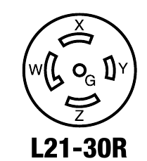
Breaker poles and receptacle poles are different counts. NEMA device poles include neutral when present; equipment ground is counted as a wire, not a pole. For example, L14 is a 3-pole/4-wire device on a 2-pole tap-off, while L21 is a 4-pole/5-wire device on a 3-pole tap-off. Neutral carries load current; equipment ground is a separate protective path and cannot replace it.
Match the breaker to the complete tap-off.
For a breakered tap-off, specify the breaker’s pole count, current rating and voltage rating to suit the receptacle, internal conductors and equipment requirements. Confirm the required interrupting rating for the installation. A 60A receptacle does not make every connected load a 60A circuit; the complete assembly must be selected for the application.
Example: a NEMA L21-20 connection uses three lines + neutral + ground. A matching 20A branch-circuit build uses a 3-pole 20A breaker—not a 4-pole breaker simply because the NEMA device is called 4-pole/5-wire.
Six female-interface examples from the Hubbell NEMA configuration chart, pages IV–V. Images identify the interface, not the component supplier or complete assembly rating. Confirm the full plug designation; appearance alone does not establish compatibility.
The connection reference
NEMA receptacle chart for track busway.
Compare 24 common straight-blade and locking configurations below. NEMA and IEC receptacle options are available up to 60A on selected T225 tap-offs; this chart is a reference to common interfaces, not the full range of available builds. Send the equipment’s exact plug designation for a matching configuration.
Read the device rating and circuit voltage separately. A 125V device commonly serves a 120V circuit; an appropriate 250V device may serve a 208V or 240V assembly. The receptacle does not change supply voltage.
For 277V, use the 1-pole L7 rows. For 480V, see 2-pole L8 or the three-phase L16 / L22 rows. Confirm T225 240V builds where the selector does not list them.
1
1-pole tap-offs: 120V or 277V
One breaker pole supplies one line conductor; a neutral and equipment ground complete the connection. The 120V options below include 40A and T225 assemblies; the 277V options are T225. Single, duplex and quad describe the outlet arrangement, not a higher circuit rating.
Device pole / wire counts include neutral where present and equipment ground in the wire count. Scroll horizontally on a small screen.
NEMA configuration
Device rating
Poles / wires
Connection
System application
Track Busway assembly
5-15
15A 125V
2 poles / 3 wires Line + neutral + equipment ground
Two breaker poles supply line-to-line loads. L6 and L8 have no neutral; L14 includes neutral. 40A options cover the named 208V / 240V assemblies. T225 options include 208V and 480V; confirm a 240V T225 build where it is not in the selector.
Device pole / wire counts include neutral where present and equipment ground in the wire count. Scroll horizontally on a small screen.
NEMA configuration
Device rating
Poles / wires
Connection
System application
Track Busway assembly
6-20
20A 250V
2 poles / 3 wires Two lines + equipment ground; no neutral
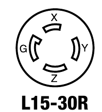
Three breaker poles supply phases A, B and C. L15 and L16 have no neutral; L21 and L22 include neutral for their specified wye systems. All eight configurations below are available on the 40A 3-phase PowerDrop with one cord-end connector and a matched 20A or 30A breaker.
Device pole / wire counts include neutral where present and equipment ground in the wire count. Scroll horizontally on a small screen.
NEMA configuration
Device rating
Poles / wires
Connection
System application
Track Busway assembly
L15-20
20A 250V AC, 3-phase
3 poles / 4 wires Three lines + equipment ground; no neutral
Product links identify assembly families. Confirm the final receptacle, breaker, grounding and enclosure combination in the selected factory build.
IEC 60309 · T225
IECPin-and-sleeve connections up to 60A
A connection for your rack PDU or equipment.
Selected T225 outlet-box and PowerDrop builds support IEC pin-and-sleeve receptacles and cord connectors. Match the manufacturer part number, current, voltage, conductor arrangement and earth-contact clock position.
Wiring reference for selecting a compatible IEC device. These arrangements are not a list of stock tap-off configurations.
Load arrangement
Tap-off breaker
Device contacts
Selection check
Line to neutral
1 pole
2P + E (3 contacts)
Match line-to-neutral voltage, current and earth-contact position.
Line to line
2 poles
2P + E (3 contacts); additional neutral where specified
Confirm whether the equipment requires neutral and the exact connector arrangement.
Three phase, no neutral
3 poles
3P + E (4 contacts)
Match three-phase voltage and current.
Three phase with neutral
3 poles
3P + N + E (5 contacts)
Match the PDU plug: 415Y/240V and 480Y/277V applications require their appropriate voltage and clock-position interface. Confirm the complete selected assembly.
415/416Y/240V data-center connections
A 240V equipment load may be supplied from one phase and neutral on a nominal 415/416Y/240V wye system. A rack PDU may instead take all three phases and neutral, then distribute 240V internally. These are different tap-off arrangements.
For existing NEMA equipment, identify the complete mating plug and the equipment wiring requirements. L6 devices are rated 250V; L7 devices are rated 277V and have a different interface. Supply voltage or breaker-pole count alone does not determine the correct receptacle. Project-specific line-to-neutral builds are coordinated separately from the standard selector options above.
For IEC equipment, provide the full manufacturer part number, such as the specified 60A 3P+N+E rack-PDU plug, plus its voltage and clock position. We will confirm the mating integral receptacle or cord connector, breaker arrangement and finished tap-off ratings. Explore data-center busway and A/B rack-power layouts →
The T225 Intertek report covers selected pin-and-sleeve components rated 20–60A and 100–480V. Component coverage does not establish every finished tap-off combination. Review T225 listing details.
For the specification
The details that make the match.
40A phase connections & C-phase whips
Choose the receptacle to match the equipment plug, then choose the phase connection for the available supply. The receptacle designation and the phase selector describe different parts of the assembly.
120V, one pole: select A or B - Standard for a single deck or either lower-deck phase on a double-deck three-phase system. C - Whip reaches upper-deck C. Both use one phase and neutral.
208V, two poles: A and B - Standard uses the lower deck; B and C - Whip uses lower-deck B and upper-deck C. Both supply 208V line to line on a 208Y/120V system.
240V, two poles: the 240V product pages use A and B with the matching 120/240V supply. A whip does not change supply voltage.
The one- and two-pole C-phase whip configurations use the -WP part-number suffix. The 3-phase PowerDrop includes its upper-deck C whip as part of the assembly. Review the selected product’s wiring diagrams and available configurations before ordering.
Grounding & neutral: 40A vs. T225
40A: housing ground
The 40A system uses housing ground, with no isolated-ground or 200% neutral option. Taps are rated up to 40A; the selected breaker, device and assembly may have lower ratings.
Compatible IG builds add an insulated grounding path; the metal housing remains grounded. Match IG through the feed, busway, joiners and tap-off. The separate 200% neutral option does not increase phase or tap-off ratings.
Compact (C) and Standard (S) enclosures accommodate different receptacle counts, breaker types and monitoring equipment. Depending on the factory build, Compact units support up to two outputs and Standard units up to three. Multiple outputs share the tap-off capacity; they do not multiply it.
T225 tap-offs support up to 60A per phase across the unit, subject to the selected assembly and branch protection. Available protection includes MCB, MCCB or CubeFuse by configuration. Use the selected product specifications and data sheet for the exact enclosure, protection, output count and cord details.
T225 critical power monitoring
Selected T225 configurations offer Schneider Electric PM5000- or HDPM6000-based critical power monitoring. Monitoring is not offered with the 40A system. Compare monitoring options →
Receptacle vs. cord connector: R and C suffixes
A female cord connector may use the same NEMA R interface designation as a mounted receptacle. The C suffix in the new 40A PowerDrop catalogue identifies the cord-connector style. Match the manufacturer part number and physical device; do not substitute suffixes.
The 40A 3-phase PowerDrop uses one locking cord connector and a matched 20A or 30A, 3-pole breaker.
USA TrackBusway · T225
Tap-Off Pre-Energization Verification Checklist
For qualified personnel verifying a T225 outlet-box or PowerDrop connection to a rack PDU before initial energization. Use this checklist with the current T225 manual, selected assembly documentation, rack-PDU instructions and approved project drawings.
Product images show example assemblies. Verify the installed unit’s markings and selected-build documents. The checklist supports initial de-energized commissioning; it is not authorization to perform energized work.
1. Establish safe inspection conditions.
De-energize the busway, follow the applicable lockout/tagout procedure and verify absence of voltage before inspection. Keep the tap-off breaker OFF. Switching that breaker OFF does not establish that the busway is de-energized. Follow the T225 installation guidance.
2. Identify the actual installed assembly.
Record the busway family, tap-off catalog number, marked voltage/current, short-circuit current rating and protective-device configuration. Confirm these match the approved selection and supporting documents. T40 and T225 tap-offs are not interchangeable; the T225 system designation is not the tap-off’s current rating. See the system compatibility guidance.
3. Check the supply, protection and approved loading.
Match the documented supply voltage, phase arrangement and neutral requirement to the rack-PDU input. Verify the selected breaker’s poles, voltage, current and interrupting rating against the approved design. Confirm the load schedule accounts for the applicable continuous-load limits and all outputs sharing the assembly. Use the selected-build ratings guidance.
4. Match the complete connector interface.
For NEMA connections, record the full mating plug/receptacle designation. For IEC 60309 connections, record the manufacturer part numbers, current, voltage, contact arrangement and earth-contact clock position. Check the exact rack-PDU input; appearance or amperage alone does not establish compatibility. Use the NEMA and IEC references.
IEC example. T225 tap box with a 560R6 receptacle, from the existing receptacle guide. Confirm the selected device’s full part number, voltage, current, contact arrangement and clock position.NEMA example. T225 outlet box with an L21-20 receptacle, from the existing receptacle guide. Match the full mating designation and selected assembly ratings to the rack-PDU input.
5. Verify the cord and equipment connection.
Confirm whether the approved connection uses an enclosure-mounted receptacle or a PowerDrop cord connector. Match the cord assembly and mating interface to the PDU manufacturer’s requirements. Check cord condition and secure factory-installed grips and strain relief. Do not modify these components to make a connection fit. See the connection and installation guides.
PowerDrop example. T225 enclosure and cord exit; the cord-end connector is not shown. Verify the actual cord, factory strain relief and mating connector against the approved build.
6. Confirm neutral, grounding and bonding.
Verify that the selected conductor arrangement matches the approved drawings through the feed, busway, joints, tap-off and equipment connection. Where isolated ground is specified, confirm the compatible insulated path while retaining housing grounding. Refer to the grounding and neutral guide.
7. Verify installation and mechanical security.
Confirm the tap-off is away from joints and housing couplers, fully inserted and securely locked. Check its position and mounting-anchor torque against manual Step 5. Confirm there are no damaged, altered or loose components and that required labels are legible. Complete the separate busway pre-energization checklist, including supports, joints, feed connections, grounding, covers and end caps. See the T225 installation checklist.
Installation and locking reference. Existing illustration from the T225 installation guide, corresponding to manual revision 1, sheet 2, Step 5. Open the image to inspect the callouts; follow the complete manual and instructions applicable to the selected assembly.
8. Close outstanding checks before release.
Record completion of the electrical and functional tests required by the applicable manufacturer instructions and approved commissioning plan. Resolve mismatched markings, missing documents, defects and failed checks before energization. Test methods, acceptance limits and the switching sequence must come from those controlled instructions.
No. Receptacles and connectors are supplied as part of configured Track Busway tap-offs, outlet boxes, PowerDrop cords or in-fitter products.
Can I get 5-20R single, duplex or quad outlets?
Yes. Applicable 120V products offer 5-20R single, duplex and quad arrangements. Outlet count does not increase circuit capacity. Use the 5-20 connection row to reach the available product families.
Are L5-30R and L6-30R available?
Yes, named T225 builds include both. L5-30R is a 30A, 125V device used for 120V one-pole connections; L6-30R is a 30A, 250V device used for selected 208V or project-specific 240V two-pole connections. Confirm a 40A-system 30A factory build where it is not in the selector.
Can I move a receptacle connection later?
Compatible tap-offs can be repositioned according to the system installation instructions. Use qualified personnel and the applicable installation guide; do not modify internal components to change the configuration.
Bring it together
Three steps to the right tap-off.
01 · Match the equipment.Record the complete plug designation, voltage, current, phase, neutral and grounding needs. These determine the receptacle or cord-end connector.
02 · Match the busway system.Choose T40-compatible or T225-compatible tap-offs. Confirm the receptacle’s conductors, matching breaker poles and rating, and the assembly’s marked limits.
03 · Choose outlet box or drop cord.Keep the receptacle on the enclosure, or bring it to the equipment on a cord. Specify outlet count, cord length and any supported monitoring.
Have a plug to match?
Send its full designation, a nameplate photo and your project layout. We’ll help confirm the connection and complete tap-off assembly.


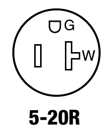 5-20R
5-20R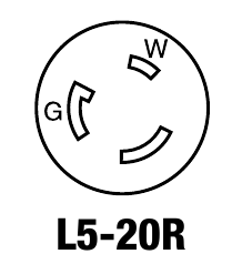 L5-20R
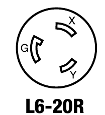 L6-20R
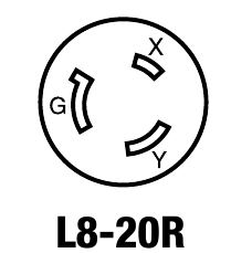 L8-20R
 L21-30R
 L15-30R
