
225A Track Busway for Higher-Capacity Power

USA TrackBusway T225 is a three-phase, continuous plug-in busway system rated up to 225A per phase and 600V.
Its open-channel design accepts repositionable 1-pole, 2-pole, and 3-pole tap-off units rated up to 60A per phase, allowing power to be added or relocated anywhere along the run.
Available conductor configurations include Standard, 200% Neutral, Isolated Ground, and 200% Neutral + Isolated Ground.
Listed to UL 857 busway standards.
Watch the 225A Track Busway Installation
See the T225 system suspended, joined, fed, and equipped with repositionable tap-off units.

Need More Than 225A per Phase?
Use splitter-based layouts to serve two separately coordinated 225A runs or zones from one distribution point. Each run remains 225A per phase; source capacity, section boundaries, overcurrent protection, conductor continuity, available fault current, load, and redundancy must be reviewed for the project.
Planning or Comparing a 225A Busway Layout?
Need help planning the 225A system, feed locations, tap-offs, or project layout?
Download the 225A Track Busway Installation, Operation & Maintenance Manual (PDF)
Revision 1 · August 1, 2026 · 3 sheets
T225 System Quick Facts
-
225A per phase
Up to 225A per phase for three-phase, 50/60 Hz systems.
-
Listed configurations up to 600 Vac
cETLus Listed configurations evaluated by Intertek to UL 857 and CSA C22.2 No. 27. Control No. 5011082.
-
Conductor options
Available conductor configurations include Standard, Isolated Ground, 200% Neutral, and 200% Neutral + Isolated Ground.
-
Tap-off configurations
Compatible T225 tap-off units can support 1-pole, 2-pole, and 3-pole load configurations.

How the 225A Track Busway System Is Assembled
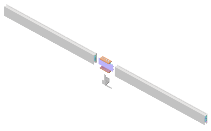
Pre-assembled straight sections are joined on-site using mechanical and electrical joiners, then powered through feed enclosures. Plug-in power units are installed at compatible plug-in locations selected for the project layout to deliver overhead power where it is needed.
-
 JOINERs
Join Track Busway Sections
Track Busway straight sections connect using mechanical joiners to create a continuous overhead power run
-
 FEEDs
FEEDsAdd Power Feed Enclosure
A feed enclosure connects the busway run to the building electrical supply.
-

Install Plug-In Power Units
Plug-in units attach at compatible locations along the run to deliver power to equipment or lighting below.


Build a 225A Track Busway Run
A complete T225 run uses coordinated 5 ft or 10 ft sections, feeds, joiners, suspension hardware, end caps, and compatible tap-off units. Match quantities, conductor configuration, feed locations, supports, branch protection, and tap-off selections to the project drawings and approved bill of materials.


Inside the 225A Track Busway System
T225 uses insulated copper conductors in an extruded aluminum housing with a continuous access slot for compatible plug-in units. This supports overhead distribution and repositionable power access along the run.
Use T225 for flexible point-of-use distribution. Feeder busway or bus duct remains appropriate for fixed backbone connections between major electrical equipment.
225A Compatible Plug-In Units
T225 Power Tap-Off Units
Select project-specific 1-, 2-, or 3-pole drop-cord or outlet-box tap-offs. Branch protection may use a UL 489 circuit-breaker pathway or a Class CF CubeFuse pathway with the specified holder or disconnect. Exact manufacturers, models, ratings, and configurations must match the approved project documentation.
View T225 Tap-Off Units
T225 Tap-Off Load Configurations
After the 225A busway run is planned, select tap-off units by load configuration. Pole count describes the tap-off breaker/load configuration, not the total number of conductors in the busway.
-
1-Pole Tap-Off Units
For line-to-neutral loads. Use where the load requires one phase conductor and a neutral.
Drop Cord UnitOutlet Box Unit -
2-Pole Tap-Off Units
For line-to-line loads. Use where the load is supplied from two phase conductors and does not require a neutral.
Drop Cord UnitOutlet Box Unit -
3-Pole Tap-Off Units
3PNG indicates 3-phase with neutral and ground. 3PG indicates 3-phase with ground and without neutral. Do not use no-neutral configurations for line-to-neutral loads.

Optional Critical Power Monitoring for 225A Track Busway
Optional monitoring may be specified at feeds or tap-offs. Confirm the hardware, power supply, communications interfaces, supported functions, and applicability in the approved project submittal.
Where 225A Track Busway Is Used
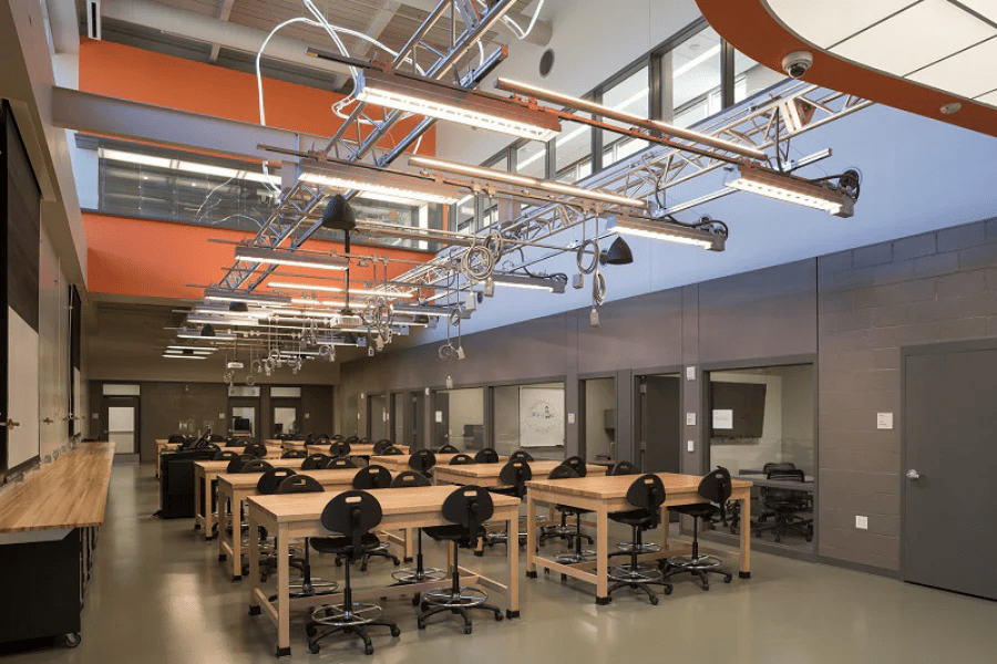
225A Track Busway is used where overhead power distribution must support heavier equipment, changing layouts, or multiple equipment zones. Common applications include data centers, industrial manufacturing plants, logistics and distribution facilities, automotive assembly areas, robotics cells, research laboratories, and flexible commercial environments where equipment layouts evolve over time.
-

Industrial
Manufacturing rows and assembly lines
-

Automotive
Robotics and automation cells
-

Data Centers
Rack rows and mission-critical equipment zones.
-
Laboratories
Laboratories and pilot production environments


Designing a Track Busway Layout
Engineers can design Track Busway layouts using the resources available on TrackBusway.com, including installation guidance, BIM tools, and complimentary layout drawings prepared from project ceiling plans.
Planning and Lead Times
Because 225A layouts are project-specific, lead time can vary based on configuration, order size, feed placement, conductor options, and engineering review. For current lead-time guidance, review the Lead Times page or contact USA TrackBusway during the planning phase.
Frequently Asked Questions
No. T225 is listed for use up to 600V. 208Y/120V is one supported project configuration when the selected conductor configuration and source support it.
Use 40A Track Busway for smaller loads, lighting, and support areas. Consider T225 for higher-capacity rows and equipment zones requiring up to 225A per phase. Final selection depends on load, voltage, feed strategy, available fault current, and project drawings.
Isolated-ground receptacles may be specified on supported factory-assembled tap-offs. Confirm the busway, feed, tap-off, receptacle, and protective-device combination in the approved project submittal.
