
40A Track Busway system
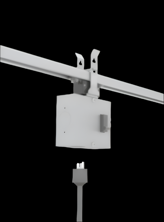
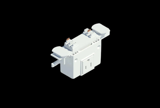
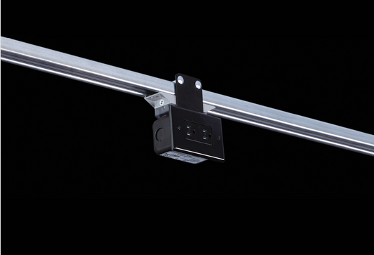
T40 120V Breakered Outlet Box


Specifications
| Phase | Single-Phase |
|---|---|
| Voltage | 120V |
| Amperage | 15A / 20A / 30A |
| Pole Count | 1 |
| NEMA | 5-20R, L5-15, L5-20, L5-30 |
Interactive 3D Preview
Changing the preview does not change your product selection.
Drag or use arrow keys to rotate. Scroll or pinch to zoom.
This 120V breakered outlet box provides a plug-in power connection on a compatible steel Track Busway run. Its integrated breaker and receptacle keep the connection at the point of use for overhead equipment layouts.
Place the outlet where the equipment’s own supply cord can reach the run. Allow space to connect and disconnect the plug without interfering with nearby equipment or overhead services.
Build your tap-off
Choose each option below to confirm your tap-off and price, then review the downloads and specifications for your build.
Catalogue number MD40-2-120-CB20-OB-SB-G
Couldn't load pickup availability
Documents for your selected tap-off
Product family cut sheets and Revit resources. Check that the document or model covers your selected configuration.
ETL Listed to UL 857 Busway Standards
For 40A Track Busway system models and configurations covered by the listing.
See T40 120V Breakered Outlet Box in Action
T40 120V Breakered Outlet Box Wiring Diagrams
Single-Deck Wiring: 120V Outlet Box
The standard 1-pole connection shown takes phase A and neutral. On a double-deck three-phase 40A system, standard units access lower-deck A or B; accessing upper-deck C requires the corresponding whip configuration.

Double-Deck Wiring: C Phase with Whip
Select C - Whip above for this double-deck configuration. The included whip reaches upper-deck C while neutral is taken from the lower deck. Phases A and B remain on the lower deck for standard units. The selected C-phase SKU ends in -WP.

Part of the 40A Track Busway System
This breakered outlet box provides a receptacle connection at a compatible 40A Track Busway run. Build the supply path with 40A track busway lengths and the appropriate power feed.
Match the selected tap's voltage, phase connection and breaker rating to the supply and equipment. Use the Track Busway system design guide to plan the complete layout.


Planning equipment additions along a busway run
Map current equipment and likely future stations before finalizing tap-off positions. Record which loads will operate together and where machines need service access; an available connection position alone does not establish spare electrical capacity.
Keep a schedule of installed tap-off catalogue numbers and the equipment they serve. When a workstation changes, review its supply and connection needs before reusing an existing assembly.
 Overhead Power DistributionExplore Applications & Projects
You may also like


- Choosing a selection results in a full page refresh.
- Opens in a new window.
