
225A Track Busway Suspension Hanger


T225 Hanger Installation
See the suspension hanger engage the upper busway channel and support the run.
Interactive 3D Preview
Drag or use arrow keys to rotate. Scroll or pinch to zoom.
T225 Hanger Installation
See the suspension hanger engage the upper busway channel and support the run.
H225-S suspension hangers secure 225A Track Busway to overhead threaded-rod supports through the upper mounting channel. Plan quantities and support locations from the run layout.
SKU: Catalogue # (SKU): H225-S
Component of the ETL Listed T225 System
For use in the listed T225 system evaluated to UL 857 and CSA C22.2 No. 27.
Intertek Control No. 5011082
Report No. 106508638CRT-001
How to Choose
Use hangers to support the busway at required intervals and maintain alignment. Hanger quantity should be calculated from the final run length and field support conditions.
Couldn't load pickup availability
Technical Downloads
Overhead Support and System Compatibility
Plan suspension hardware as part of the complete busway route. Hanger positions establish the elevation and alignment of the run and must suit the available structure, selected support method, and approved drawings.
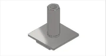
The product views show the complete hanger, the hardware exposed with the barrel coupling nut removed, its underside, and its installed position in the busway channel. Review these with the installation video and system manual when coordinating threaded rod, strut, or other compatible field support hardware. Confirm what the building support arrangement requires before finalizing quantities.


225A System Certification
The suspension hanger assembly is included in the 225A system certification report. The system is listed by Intertek to UL 857 and CSA C22.2 No. 27.
Intertek Control No. 5011082. Report No. 106508638CRT-001.
T225 Suspension Hanger Specifications
| System | 225A Track Busway |
|---|---|
| Function | Supports and aligns suspended busway runs |
| Mounting Use | Overhead suspension from threaded rod, strut, or compatible structure |
| Recommended Spacing | Follow project drawings; generally no more than 10 ft between supports unless engineering requires closer spacing |
| Used With | 225A busway lengths, feeds, and system runs |
Planning Suspension Hanger Placement
Calculate the hanger quantity from the final run length and the support locations available on site. Maintain the required alignment across adjoining sections and coordinate suspension with feeds, joins, and other components in the layout.
Follow the project drawings and current installation requirements for spacing. Where structural conditions or the electrical design require additional support hardware, include it in the project plan rather than assuming the hanger alone completes the building connection.


Frequently Asked Questions
Support spacing should follow the approved project drawings and field conditions. As a general planning rule, supports should typically be no more than 10 ft apart unless engineering or field conditions require closer spacing.
Yes. Final hanger spacing can vary based on the building structure, run length, transitions, load conditions, seismic or local requirements, and installer or engineer direction.
No. Suspension hangers are selected as supporting components and should be ordered in the quantity required for the final layout.
Final support locations should be determined by the project drawings, field installer, and engineer of record or authority responsible for the installation.


