Track Busway Tap-Off Units and Plug-In Power Devices
USA TrackBusway tap-off units and plug-in power devices deliver power from an overhead Track Busway run to equipment, receptacles, workstations, lab benches, production areas, and other point-of-use loads. Use this guide to choose between 40A tap-off units, T225 / 225A tap-off units, PowerDrop cords, outlet boxes, receptacle-in-fitter products, voltage and pole configurations, breaker protection, receptacle families, grounding options, and monitoring options.
Choose a Tap-Off Product Path
40A Tap-Off Units
Shop 40A-compatible PowerDrop cords, outlet boxes, receptacle-in-fitter products, and voltage-specific plug-in power devices.
T225 / 225A Tap-Off Units
Configure higher-capacity breakered tap-off units for compatible 225A Track Busway layouts.
PowerDrop Cords
Bring receptacle access down from the overhead busway toward equipment, benches, or workstations.
Outlet Boxes
Keep receptacle access mounted directly at the busway tap-off location.
Receptacle-in-Fitter
Use a compact 120V plug-in receptacle style where that specific product is supported.


Supplying Power Where You Need It
Track Busway provides suspended power distribution that delivers reliable electrical connections directly above the workspace. Because power is supplied overhead, equipment can be repositioned without cutting conduit or pulling new wiring.
By delivering power exactly where it is needed, Track Busway reduces floor congestion, long cord drops, and wall-mounted outlet limitations. This makes the system ideal for environments where layouts change frequently and power access must remain close to the point of use.
Track Busway uses an open-slot busway design with insulated conductors inside a steel channel. Compatible plug-in devices can be placed at supported connection points along the run, subject to system compatibility, electrical limits, safety procedures, project specifications, and qualified installation practices.
What Is a Track Busway Tap-Off Unit?
A busway tap-off box is a plug-in unit that connects to the busway conductors and delivers branch-circuit power to equipment, receptacles, or drop cords. Contractors and specifiers may also use terms such as bus plug, tap-off box, plug-in unit, power drop, or busway tap box. How bus plugs and tap-off units connect to plug-in busway.
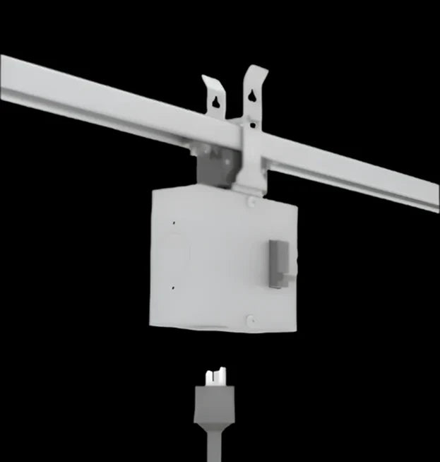
In USA TrackBusway layouts, tap-off units are selected by system compatibility, voltage, pole count, receptacle type, breaker requirements, grounding configuration, and physical device style. Breakered tap-off units may be installed, removed, relocated, and reinstalled while the busway remains energized. Before installation or removal, switch the tap-off unit’s integral circuit breaker OFF. Keep the breaker OFF throughout installation, removal, relocation, and reinstallation; do not energize the connected equipment during this work. Switch the breaker ON only after the tap-off unit has been fully installed or reinstalled and secured. This procedure must be performed by qualified personnel in accordance with USA TrackBusway instructions, project requirements, and applicable electrical codes.
PowerDrop Cords vs Outlet Boxes vs Receptacle-in-Fitter
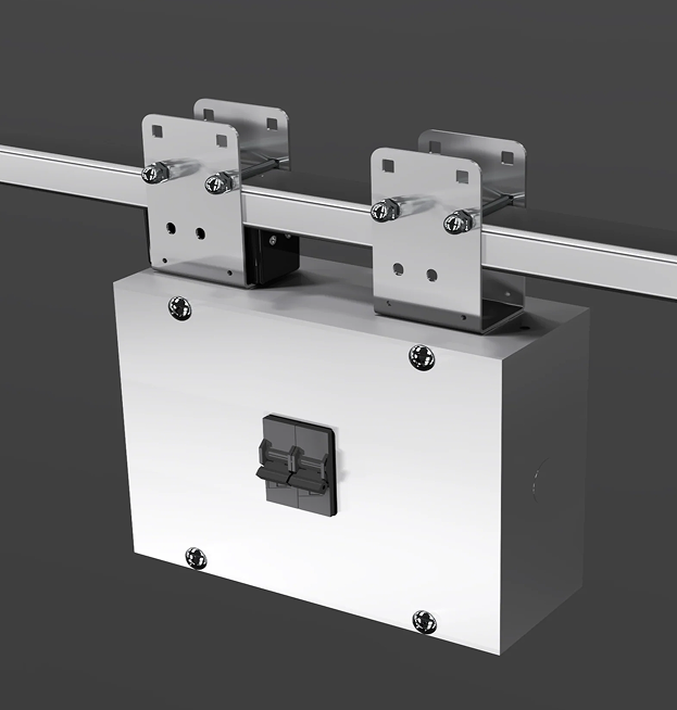
Choose the device style based on where the receptacle should be located and how the load is served. PowerDrop cords bring receptacle access down from the overhead busway. Outlet boxes keep receptacles mounted at the busway. Receptacle-in-fitter products provide compact 120V access where supported. T225 drop cord and outlet box units are separate configured tap-off assemblies for compatible 225A Track Busway systems.
-
PowerDrop cords bring receptacle access down from the overhead busway toward the equipment or workstation below. They are useful when the connection point needs to hang below the busway run.
-
Outlet boxes keep receptacles mounted directly at the tap-off location on the busway. They are useful when power should remain overhead or when a fixed box-style connection is preferred.
-
A receptacle-in-fitter is a compact plug-in receptacle device for simple 120V access where supported. It should be treated as a specific product style, not as a replacement for every outlet box or drop-cord configuration.
T225 breakered drop cord and outlet box units are configured tap-off assemblies for the 225A Track Busway system compatibility. They are selected by pole count, voltage, receptacle, breaker, grounding, enclosure, and monitoring requirements.
40A vs T225 / 225A Tap-Off Units
Use 40A tap-off units for compatible 40A Track Busway layouts with standard overhead power-access needs. Use T225 / 225A tap-off units where the project requires higher-capacity distribution, configured breaker options, larger receptacle families, grounding coordination, enclosure selection, or optional monitoring. Do not treat 40A and T225 tap-offs as interchangeable.
1-Pole, 2-Pole, and 3-Pole Configurations
Pole count describes the tap-off load and breaker configuration. It does not necessarily describe the total number of conductors in the busway run.
1-pole tap-off units are typically used for line-to-neutral loads such as 120V or 277V where supported. 2-pole tap-off units are typically used for line-to-line loads such as 208V, 240V, or 480V where supported. 3-pole tap-off units are used for three-phase loads and must be coordinated with the source, busway, receptacle, grounding, and connected equipment requirements.
Final selection should be confirmed against the project voltage system, load type, receptacle, breaker configuration, electrical drawings, and applicable code requirements.
Voltage Compatibility: 120V, 208V, 240V, 277V, and 480V
Do not select a tap-off by voltage alone. Confirm busway system, source voltage, phase, pole count, receptacle, breaker protection, grounding, and connected load.
Plug-in pole count refers to the breaker configuration, while busway pole count refers to the phase conductors in the system.
For example, a 3-pole plug-in may be installed on a four-conductor (3-phase, L-L-L-N) Track Busway to serve three-phase loads with a neutral present.


Breakered vs Unbreakered Tap-Off Options
Some 40A devices are breakered and some rely on protection elsewhere in the design. T225 units are configured protected assemblies. Confirm breaker type, rating, and protection strategy before ordering.
NEMA / IEC Receptacle Options
Select receptacles as part of the complete tap-off device, not as loose parts. Use the receptacle options page for deeper NEMA / IEC guidance.
Grounding, Isolated Ground, N2, and N2IG Options
Grounding, isolated ground, N2, and N2IG must be coordinated across the busway, feed, tap-off, receptacle, field wiring, and project design. Do not present IG, N2, or N2IG as default on every product.
Critical Power Monitoring Options
Monitoring is project-specific. Confirm meter location, meter architecture, display/network requirements, enclosure impact, and tap-off compatibility.
Technical Reference
Use these reference tables after choosing the basic tap-off path. Confirm final selections against product options, cut sheets, project drawings, code requirements, and qualified electrical review.
Compatibility Checklist
Before selecting a tap-off unit, confirm:
- Track Busway system: 40A or T225 / 225A.
- Source voltage and phase.
- Pole configuration: 1-pole, 2-pole, 3-pole, or three-phase plus neutral where applicable.
- Physical device style: PowerDrop cord, outlet box, receptacle-in-fitter, or T225 configured tap-off.
- Breaker protection requirements.
- Receptacle or connector body.
- Grounding configuration: standard, IG, N2, or N2IG where supported.
- Monitoring requirements.
- Connected load, amperage, and equipment plug.
- Project drawings, code requirements, and qualified installation practices.
40A vs T225 / 225A System Compatibility
| Feature | 40A Track Busway | T225 / 225A Track Busway | Notes |
|---|---|---|---|
| Typical branch circuit size | Common tap-off configurations include 15A, 20A, and 30A product options; system rated up to 40A per phase where configured. | Configured tap-off builds may include 15A, 20A, 30A, and selected 60A options; busway rated 225A per phase. | Confirm exact amperage by product selector, cut sheet, and project design. |
| Tap-off types | PowerDrop cords, outlet boxes, receptacle-in-fitter, voltage/pole-specific plug-ins. | Breakered drop cord tap-off units and breakered outlet box tap-off units. | Do not treat 40A and T225 tap-offs as interchangeable. |
| 1-pole support | Yes, commonly 120V line-to-neutral; confirm product. | Yes, 120V or 277V line-to-neutral where configured. | Coordinate neutral and grounding. |
| 2-pole support | Yes, commonly 208V or 240V line-to-line. | Yes, 208V, 240V, or 480V line-to-line where configured. | Confirm no-neutral vs neutral requirements. |
| 3-pole / three-phase support | Yes, selected 3-phase configurations. | Yes, selected 3-pole configurations. | Confirm source, receptacle, and load requirements. |
| Voltage range | 120V, 208V, 240V, and selected 3-phase configurations such as 208Y / 480Y where configured. | Listed up to 600V; examples include 120V, 277V, 208V, 240V, 480V, and 3-phase configurations where supported. | Do not select by voltage alone. |
| Breaker protection | Available on selected drop cords and outlet boxes; some outlet boxes are unbreakered. | T225 tap-off family is breakered / protected by configuration. | Confirm protection strategy with electrical design. |
| Isolated ground | Project-specific / selected configurations only; do not present as universal. | Supported where specified on compatible configurations. | Coordinate with feed, busway, receptacle, and field wiring. |
| N2 / N2IG | Not a standard 40A default; confirm any project-specific support. | Supported as project-specific 225A / T225 conductor configurations where available. | Coordinate full component chain. |
| Monitoring | Project-specific; confirm supported locations. | Optional on selected T225/feed/tap-off configurations. | Avoid implying all tap-offs include monitoring. |
| Typical applications | Workstations, labs, commercial, light industrial, flexible overhead power. | Higher-capacity industrial, lab, data center, automation, mission-critical, and larger-load layouts. | Final selection depends on load, voltage, layout, and drawings. |
Tap-Off Device Style Comparison
| Device style | Description | Typical use | Compatible system | Link target |
|---|---|---|---|---|
| PowerDrop / drop cord | Corded plug-in tap-off that brings receptacle access below the busway. | Benches, workstations, tools, movable equipment, production areas. | 40A and T225 styles exist; use matching system. | /collections/drop-cords |
| Breakered outlet box | Box-style tap-off with integrated breaker protection where configured. | Overhead receptacle access mounted directly at the busway. | 40A selected products and T225 configured units. | /collections/outlet-boxes |
| Receptacle-in-fitter / plug-in unit | Compact plug-in receptacle device for supported 120V applications. | Simple localized 120V power access. | 40A product path; confirm exact product support. | /products/receptacle-in-fitter |
| T225 breakered drop cord | Configured protected drop cord tap-off for 225A Track Busway. | Higher-capacity or coordinated 225A layouts needing corded receptacle access. | T225 / 225A only. | /collections/t225-power-tap-off-units |
| T225 breakered outlet box | Configured protected outlet-box tap-off for 225A Track Busway. | Higher-capacity or coordinated 225A layouts needing box-mounted receptacles. | T225 / 225A only. | /collections/t225-power-tap-off-units |
| Feed unit | Power-entry component that brings source power into the busway; not a tap-off unit. | Supplying the busway run from the building electrical system. | 40A feeds or 225A feeds, depending on system. | /collections/feeds /products/225a-track-busway-power-feed-units |
Pole / Voltage Matrix
| Pole configuration | Typical voltage | Load type | Example tap-off type | Notes |
|---|---|---|---|---|
| 1-pole line-to-neutral | 120V | Convenience power, tools, workstations, lab bench loads. | 120V PowerDrop cord, 120V outlet box, T225 1-pole unit. | Confirm neutral and grounding requirements. |
| 1-pole line-to-neutral | 277V where applicable | Lighting-related or project-specific line-to-neutral loads. | T225 1-pole configured tap-off. | Use only where source and product configuration support it. |
| 2-pole line-to-line | 208V | Single-phase equipment loads. | 208V PowerDrop cord, 208V outlet box, T225 2-pole unit. | No neutral unless specifically required by configuration. |
| 2-pole line-to-line | 240V | Single-phase equipment loads. | 240V PowerDrop cord or outlet box where configured. | Confirm receptacle and breaker compatibility. |
| 2-pole line-to-line | 480V where applicable | Higher-voltage line-to-line loads. | T225 2-pole configured tap-off. | Confirm product selector and engineering review. |
| 3-pole / three-phase | 208Y or 480Y where configured | Three-phase equipment. | 3-phase PowerDrop cord, 3-phase outlet box, T225 3-pole unit. | Confirm whether neutral is required. |
| 4-pole / three-phase plus neutral | 208Y/120V or 480Y/277V system context where applicable | Three-phase systems with neutral available. | Use compatible 3-pole/3-phase tap-offs only where specified. | Treat as system/conductor context, not a generic standalone tap-off product. |
Receptacle / Outlet Option Summary
| Receptacle category | Typical voltage | Typical amperage | Typical tap-off style | Notes | Link target |
|---|---|---|---|---|---|
| NEMA 5 straight-blade | 120V | 15A / 20A | 120V drop cord, outlet box, receptacle-in-fitter | Examples may include 5-15R, 5-20R, duplex, or quad where the product selector supports them. | /pages/receptacle-options |
| NEMA L5 locking | 120V | 15A / 20A / selected 30A where configured | Drop cord, outlet box, T225 configured tap-off | Do not present L5-30R as standard 40A unless confirmed for that product. | /pages/receptacle-options |
| NEMA L6 locking / 6-series | 208V / 240V | 15A / 20A / selected 30A where configured | 2-pole drop cord, 2-pole outlet box, T225 configured tap-off | L6-30R should be treated as T225/project-specific unless the product selector confirms. | /pages/receptacle-options |
| NEMA L15 / L16 | 3-phase | Typically 20A / 30A where configured | 3-pole / 3-phase tap-off | Confirm exact voltage, grounding, and product support. | /pages/receptacle-options |
| NEMA L21 / L22 | 3-phase plus neutral | Project-specific | T225 configured tap-off | Use only where neutral, voltage, and receptacle family are supported. | /collections/t225-power-tap-off-units |
| IEC / pin-and-sleeve | Project-specific; often higher-amperage configured use | Selected 60A options where supported | T225 configured tap-off | Confirm exact IEC family, grounding, voltage, and build selection by project review. | /collections/t225-power-tap-off-units |
| Live ends / connector body | Project-specific | Project-specific | Selected drop cord or configured assembly | Avoid treating as a receptacle default; confirm use case and safety requirements. | /pages/contact |
Grounding / Monitoring Availability Summary
| Option | 40A System | T225 / 225A System | Notes | Link Target |
|---|---|---|---|---|
| Standard grounding | Common standard configuration. | Common standard configuration. | Confirm grounding path across busway, feed, tap-off, receptacle, and field wiring. | /pages/grounding-isolated-ground-200-neutral |
| Isolated ground / IG | Project-specific / selected supported configurations only. | Supported where specified on compatible configurations. | Do not present as default on every product. | /pages/grounding-isolated-ground-200-neutral |
| N2 | Do not present as standard 40A feature. | Project-specific 225A / T225 conductor configuration. | Coordinate with load calculations, voltage system, feed, and busway lengths. | /pages/grounding-isolated-ground-200-neutral |
| N2IG | Do not present as standard 40A feature. | Project-specific 225A / T225 conductor configuration. | Requires full component coordination. | /pages/grounding-isolated-ground-200-neutral |
| Critical power monitoring | Project-specific; confirm supported locations. | Optional on selected feed/tap-off configurations. | Monitoring page references feed and selected tap-off/drop visibility. | /pages/critical-power-monitoring |
| Breaker protection | Available on selected 40A tap-off products; not universal. | T225 tap-offs are configured as protected units. | Confirm breaker type, rating, and protection strategy. |
/collections/power /collections/t225-power-tap-off-units |
Frequently Asked Questions
A Track Busway tap-off unit is a plug-in power-access device that connects to compatible busway conductors and delivers power to a load, receptacle, outlet box, or PowerDrop cord. Selection depends on the busway system, voltage, pole count, receptacle, breaker protection, grounding, and project requirements.
Use 40A tap-off units for compatible 40A Track Busway layouts where the connected load and product ratings match the project. Use T225 / 225A tap-off units for higher-capacity or more highly configured layouts that require coordination of busway, feed, breaker, receptacle, grounding, and optional monitoring details.
Use a PowerDrop cord when receptacle access needs to hang closer to equipment, benches, or workstations below the busway. Use an outlet box when the receptacle should remain mounted directly at the busway. Use a receptacle-in-fitter only where that compact 120V product style is supported.
Pole count describes the tap-off load and breaker configuration. 1-pole units are typically used for line-to-neutral loads such as 120V where supported. 2-pole units are typically used for line-to-line loads such as 208V or 240V. 3-pole units are used for three-phase loads and must be coordinated with the source, receptacle, grounding, and connected equipment.
Yes, where the selected busway, feed, tap-off unit, pole count, breaker, receptacle, grounding, and connected load are compatible. Do not select a tap-off by voltage alone; confirm the complete electrical configuration before ordering.
Some power-access devices include integrated breaker protection, while others rely on protection elsewhere in the electrical design. T225 tap-off units are configured as protected assemblies. Confirm breaker type, rating, and protection strategy with the project electrical requirements.
These options are project-specific and are not default features on every tap-off product. Isolated ground, 200% neutral, N2IG, and monitoring should be coordinated across the busway, feed, tap-off unit, receptacle, field wiring, and project drawings.
Yes. Qualified personnel may relocate a breakered tap-off unit while the busway remains energized. Switch the unit’s integral circuit breaker OFF before removal and keep it OFF throughout removal, relocation, and reinstallation. Switch the breaker ON only after the unit has been fully reinstalled and secured. Follow USA TrackBusway instructions, project requirements, and applicable electrical codes.
Plug-In Unit Specifications
Track Busway plug-in units are available in multiple configurations to support 120V, 208V, 240V, and 480V applications across both single-phase and three-phase systems.
The summary below consolidates the key electrical characteristics of 1-pole, 2-pole, and 3-pole plug-in units, helping you quickly understand voltage compatibility, breaker configurations, and available receptacle options.
| Phase | Single-Phase / Three-Phase |
|---|---|
| Voltage | 120V (L–N) / 208V (L–L) / 240V (L–L) / 208Y (3-Phase) / 480Y (3-Phase) |
| Pole Count (Breaker Configuration) | 1 / 2 / 3 |
| Amperage | 15A / 20A / 30A |
| NEMA |
1-Pole (120V L–N):
5-15R, 5-20R, L5-15, L5-20, L5-30 2-Pole (208V / 240V L–L): L6-15, L6-20, L6-30 3-Pole (208Y / 480Y Three-Phase): L15-20, L15-30 (3P + G, no neutral) 3-Phase + Neutral (3P + N + G): L21-20, L21-30 (208Y) / L22-20, L22-30 (480Y) |
Standard Track Busway Configurations
Track Busway systems can be arranged in several overhead layouts depending on the workspace and equipment requirements. These configurations allow power to be distributed above work areas while maintaining flexible access for plug-in devices.
Choose the configuration that best matches your project layout:
-
 GRID
GRIDGRID configurations create evenly distributed overhead power across large areas. Ideal for facilities that require uniform coverage, GRIDs reduce homerun feeds and support flexible placement of power drops throughout the space.
-
 RECTANGLEs
RECTANGLE layouts provide structured perimeter and interior coverage for defined work zones. This configuration is commonly used where power needs to be evenly distributed around equipment, benches, or production areas.
-
 ROWs
ROWs