

Data Center Busway Power Distribution
Data center busway is an overhead electrical power distribution system that delivers power across rack rows, colocation suites, server rooms, support spaces, and mission-critical equipment zones. It creates an accessible power backbone above the equipment layout instead of relying on a fixed outlet path for every connection.
USA TrackBusway provides open-slot plug-in busway for layouts where rack density, tenant requirements, equipment loads, and deployment schedules may change. Feed locations, tap-off units, optional monitoring, and splitter-based layouts can be coordinated around the equipment plan.
High-Density Rack Rows Change Fast. Fixed Wiring Does Not.
AI/HPC deployments, tenant changes, equipment refreshes, and phased buildouts can change faster than fixed electrical infrastructure. Overhead plug-in busway gives project teams a more adaptable way to distribute power across rack rows and equipment zones.
What Is Data Center Busway?
Data center busway distributes power from a feed point to multiple locations along a row, room, suite, or equipment zone. Insulated conductors or busbars are enclosed in a protective housing, and compatible tap-off units, power drops, or outlet boxes connect the required loads.
For broader terminology, see the Busway Fundamentals guide.
Reduce Fixed Wiring and Underfloor Cable Congestion
Overhead Track Busway keeps feed and tap-off locations visible and accessible as rack layouts change, reducing fixed-wiring rework and underfloor cable congestion.
Removing underfloor power whips and reducing cable congestion can also help clear obstructions from underfloor or overhead airflow paths. This can support cleaner cold-air delivery and hot-aisle/cold-aisle planning, but actual cooling performance and PUE depend on the facility’s HVAC design, rack layout, containment strategy, and electrical/mechanical engineering review.
It is also important to distinguish Track Busway from high-amperage feeder busway or bus duct. Feeder busway is typically used as a power backbone between switchgear, transformers, and electrical rooms. Track Busway or plug-in busway is used for more flexible point-of-use distribution to rack rows, suites, support zones, and equipment areas.
Fixed Conduit vs. Underfloor Whips vs. Overhead Busway
| Planning Issue | Fixed Conduit / Junction Boxes | Underfloor Whips | Overhead Track Busway |
|---|---|---|---|
| Rack layout changes | Often requires rework | Can require whip relocation or replacement | Tap-off locations can be adjusted |
| New power access points | Requires new wiring paths | May require new whip routing or floor coordination | Plug-in tap-offs can be planned along the run |
| Visibility | Hidden in walls, ceilings, or underfloor paths | Often hidden below raised floor or routed out of sight | Visible and accessible overhead |
| Cooling & airflow | Usually no direct impact, but can contribute to ceiling-level or wall-routing complexity | Can add underfloor cable congestion and airflow obstructions | Keeps power distribution overhead and can help reduce underfloor cable congestion, subject to facility layout and mechanical design |
| Phased buildouts | Can be harder to modify after install | Can become harder to manage as layouts change | Easier to coordinate by row, zone, or phase |
| Monitoring | Usually added separately | Usually planned separately unless added through other equipment | Optional monitoring can be planned with the busway layout |
Higher-Capacity Overhead Power for Changing Rack Layouts
Plan T225 feeds and tap-offs around rack rows and equipment zones as loads change. Splitter layouts can serve two separately coordinated 225A-per-phase runs or zones.
A splitter does not increase a single run’s ampacity. Confirm source capacity, available fault current, upstream protection, conductor configuration, load, section boundaries, and A/B redundancy objectives for each path.
Learn how splitter layouts feed 225A busway runs left and right
Track Busway Solutions for Data Centers
-
Higher-Capacity Overhead Busway
Use 225A Track Busway for rack rows and larger equipment power needs. Plan runs around row layouts, equipment zones, feed points, and tap-off locations.
View 225A Track Busway → -
Feed Placement and Splitter Layouts
Coordinate feed locations around the electrical design. Use splitter layouts where power needs to branch to left and right 225A busway runs or support separated load zones.
Learn how splitter layouts feed 225A busway runs left and right → -
Tap-Off Units and POWER Plug-Ins
Place tap-off units near racks, cabinets, or support equipment. Use protected plug-ins, outlet boxes, or drop-cord options where the project requires them.
View T225 Tap-Off Units →

Plan the System as a Coordinated Layout
Coordinate the busway run, feeds, joiners, tap-offs, supports, and optional monitoring as one layout. Confirm facility voltage and phase, row loads, available fault current, required SCCR, branch protection, and grounding or neutral requirements before release.
Use approved project drawings to define feed and section boundaries, tap-off locations, support points, structural coordination, and required submittals.
Data Center Power Applications
-
AI and High-Performance Computing
Plan overhead power distribution for changing rack densities, equipment types, and deployment schedules as AI and high-performance computing environments evolve.
-
Edge Rooms
For smaller edge rooms, 40A Track Busway can provide flexible plug-in power where loads and layouts fit the application.
-
Colocation and Tenant Suites
Support tenant changes, phased suite buildouts, and rack-row updates with overhead plug-in busway planned around each suite’s power needs.
-
High-Density Rack Rows
Use higher-capacity Track Busway for rack rows where power density, equipment types, or deployment schedules may change. Plan 225A busway runs, feed locations, and tap-off units around the actual row layout.
-
Enterprise and Mission-Critical Facilities
Support enterprise data centers, server rooms, and critical facilities where visible power access, uptime planning, and future changes matter.
-
Phased Buildouts and Expansion
Plan feed locations, tap-off units, and splitter-based layouts around phases, rack rows, and future expansion. Use 225A Track Busway for larger layouts and higher-capacity equipment power.

Code-Reviewed Overhead Busway for Critical Environments
USA TrackBusway is designed as an overhead busway system for project-specific electrical layouts. For code-reviewed applications, Track Busway is ETL Listed to UL 857 and designed for NEC Article 368 busway applications. Final layout, load planning, overcurrent protection, and installation details are evaluated for the specific project before release.
Optional Power Monitoring for Projects That Need Visibility
Optional monitoring can be planned at feeds or tap-offs when a project requires metering, alarms, or networked data. Confirm the hardware, power supply, communications interfaces, supported functions, and applicability in the approved project submittal.
-
Monitoring Requirements
Define required measurements, alarm points, and reporting.
-
Communications
Confirm approved hardware and the required project protocol before release.
-
Submittal Coordination
Match monitoring components to the selected feed or tap-off configuration.
Planning a Data Center or Mission-Critical Power Project?
Our team can review your layout, power access requirements, and future expansion plans to determine whether overhead Track Busway is the right fit.
Optional 40A Track Busway for Lighting and Support Loads
For data center projects, use 40A Track Busway for lighting, support loads, smaller rooms, and equipment areas whose calculated loads fit the system. Consider T225 for rack rows and higher-capacity equipment zones requiring up to 225A per phase. Final selection depends on load, voltage, feed strategy, available fault current, grounding and neutral requirements, and project drawings.


Other Flexible Power Applications
USA TrackBusway also supports flexible overhead power in other environments where layouts, equipment, and work areas change over time.
-
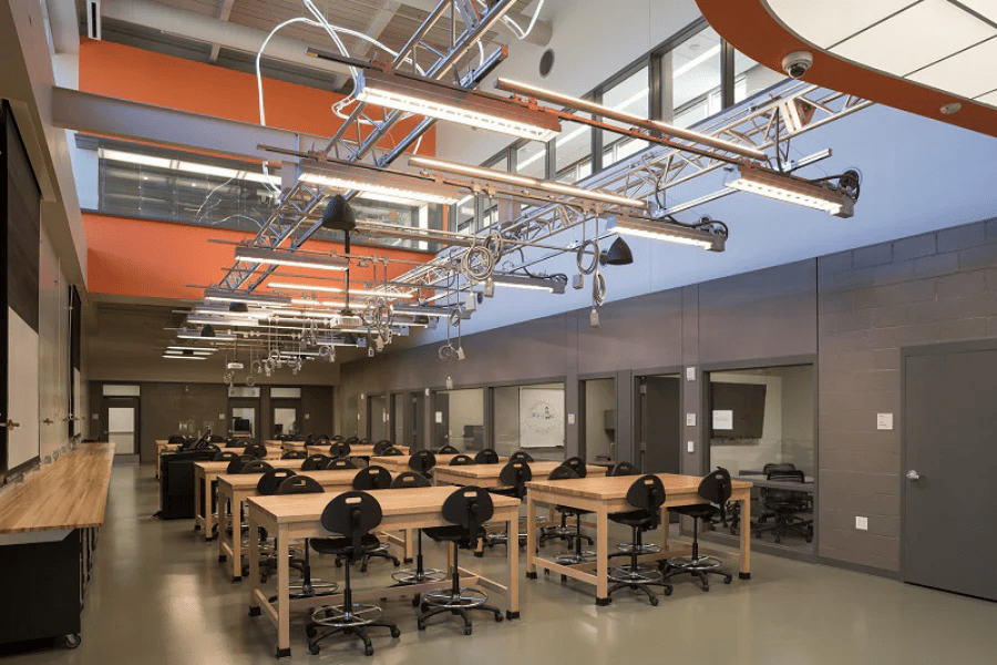
Laboratories
Flexible overhead power for lab benches, equipment zones, and research spaces that may need to be reconfigured over time.
View Laboratories Track Busway Projects -

Office / Enterprise Workspaces
Overhead plug-in power and lighting for workspaces where furniture, teams, and layouts may change.
View Workspace Track Busway Projects -

Industrial
Adaptable overhead power for production areas, tooling, workstations, and changing equipment layouts.
View Industrial Track Busway Projects -

Automotive
Flexible overhead power for assembly lines, service bays, and production areas that require efficient power distribution.
View Automotive Track Busway Projects


Coordinate feeds with source capacity, available fault current, upstream protection, voltage drop, equipment zones, maintenance boundaries, and A/B redundancy objectives. A splitter does not increase a single run’s ampacity.
Tap-off units connect equipment loads through outlet-box or drop-cord configurations. Branch protection may use a UL 489 circuit-breaker pathway or a Class CF CubeFuse pathway with the specified holder or disconnect. Exact manufacturers, models, ratings, and configurations must match the approved project documentation.
Yes. Confirm rack and row load, facility voltage and phase, available fault current, required busway and tap-off SCCR, and protective-device interrupting rating before selecting the run.
USA TrackBusway is ETL Listed to UL 857 and designed for NEC Article 368 busway applications. Final installation details should be reviewed for each project.
Use 40A Track Busway for smaller loads, lighting, and support areas. Consider T225 for higher-capacity rows and equipment zones requiring up to 225A per phase. Final selection depends on load, voltage, feed strategy, available fault current, and project drawings.
No. Data center busway layouts vary by rack density, equipment type, monitoring requirements, available source power, and whether the system is serving rack power, support spaces, lighting, or flexible equipment zones.
Overhead busway can reduce the need for underfloor power whips and cable congestion, which may help keep airflow paths clearer in raised-floor or high-density layouts. Actual cooling performance depends on the mechanical design, containment strategy, rack layout, equipment loads, and facility-specific engineering review.
