
225A Track Busway Joiner


T225 Joiner Installation
See how the electrical connector and mechanical couplers join adjacent busway sections.
Interactive 3D Preview
Drag or use arrow keys to rotate. Scroll or pinch to zoom.
T225 Joiner Installation
See how the electrical connector and mechanical couplers join adjacent busway sections.
Connect adjoining 225A Track Busway lengths with a T225 joiner. Coordinate joint locations with the run layout, power feeds and installation drawings.
SKU: Catalogue # (SKU): JK225-E-4-600
Electrical: continues the conductor path between adjoining busway sections.
Non-Electrical: joins and aligns the housings where the layout calls for electrically separate sections.
Listed to UL 857 Busway Standards
Includes JK225-E electrical and JK225-NE non-electrical joiners for the listed T225 system.
Intertek Control No. 5011082
Report No. 106508638CRT-001
Couldn't load pickup availability
Technical Downloads


Joint Assembly & Installation Tool
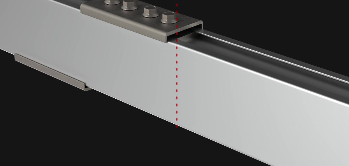
The installed view shows the mechanical couplers securing and aligning adjacent housings. Use the installation video and current manual to see how the components fit together.
The JT225-E joiner installation tool is a separate product used with the electrical connector. Include the required joiners and installation tool when preparing the project bill of materials, and use the current 225A installation manual for the assembly procedure.

T225 Joiner Specifications
| System | 225A Track Busway |
|---|---|
| Voltage | Up to 600V where applicable |
| Pole Count | 4-Pole for electrical joiner |
| Joiner Types | Electrical and Non-Electrical |
| Used With | 225A Track Busway lengths |
Plan the Joint Locations
Confirm the joint type at each connection before ordering. The 20-foot 225A row example shows how one joined connection relates to two straight sections. The connector detail shows the contact surfaces used in the electrical joint.

Matching the Busway Conductor Configuration
Coordinate the electrical joint with the busway conductor arrangement: Standard, Isolated Ground (IG), 200% Neutral (N2), or 200% Neutral + Isolated Ground (N2IG).
Confirm the compatible joint kit and conductor requirements in the approved project drawings before ordering.
Standard+ 200% Neutral
N2+ Isolated Ground
IG

Electrical Connection Detail
For electrical joiner applications, the 225A joint kit uses a bus connector to continue the conductor path between adjoining Track Busway sections.
With the adjacent busway lengths aligned, the bus connector is inserted through the continuous access slot and centered across the joint. The installation tool is then used to rotate the connector 180 degrees so the connector blades seat into the internal busbar channels.
The electrical connector should be verified as fully seated before completing the mechanical closure. Mechanical housing couplers secure the adjacent housings and help maintain alignment across the joint.
Installation Notes
- Follow project electrical drawings, engineering documents, and applicable electrical codes.
- Installation must be performed by qualified personnel.
- De-energize upstream power before making feed or electrical connections.
- Do not install plug-in units directly at the joint or housing couplers.
-

Bus connector used for the 225A electrical joiner.
-

Insert the bus connector into the access slot and center it across the joint.
-

Use the installation tool to rotate and seat the connector blades into the busbar channels.


Frequently Asked Questions
Typically, one joiner is required at each connection point between adjoining 225A busway sections. Final quantity depends on the layout, number of sections, feed strategy, and whether any non-electrical separation points are planned.
No. Joiners connect adjoining busway sections. End caps are used to close open ends of a busway run. A complete layout may require both joiners and end caps.


