
Electrical busway is a prefabricated power-distribution system made of copper or aluminum busbars inside a protective housing. Sections join together to carry electricity between equipment or along a building. Depending on the system, tap-off units deliver power to individual loads along the route.
Also called bus duct, it is used for electrical distribution. This guide explains the equipment, its main types, and how it differs from busbars and conduit.
Busway, Bus Duct, and Busbar: What's the Difference?
Busway and bus duct commonly refer to the same general equipment category. A busbar is the conductor inside that equipment. The words “bus duct” alone do not tell you whether a system is feeder, fixed-window plug-in, or continuous-access construction.
| Term | What it describes | Key distinction |
|---|---|---|
| Busway | The assembled distribution system: enclosed busbars, joints, feeds, fittings, and supports. | A complete manufactured system. |
| Bus duct / busduct | A commonly used name for enclosed-busbar distribution equipment. | Often overlaps with busway; confirm the specified construction and function. |
| Busbar | A conductive bar, typically copper or aluminum, that carries current. | A component found inside busway, switchgear, and other equipment. |
| Conduit | A raceway through which separate electrical conductors are installed. | A wiring method using separately installed conductors. |
Main Types of Electrical Busway
Start with the job the system must do: carry power between major equipment, or provide connections to loads along a route. Feeder and plug-in arrangements serve different needs; plug-in access can use fixed windows or a continuous slot.
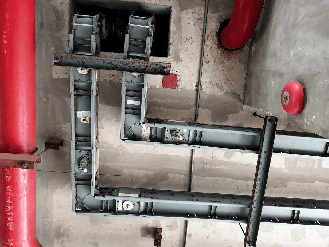
Feeder busway
Moves power between major electrical equipment or through a building's distribution backbone. Typical examples include connections between transformers and switchgear, or risers serving multiple floors.
Best suited to: a planned power route between distribution points. The specific product determines available fittings and any permitted taps.
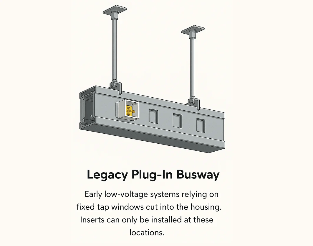
Fixed-window plug-in busway
Provides factory-made openings for compatible bus plugs or tap-off units. Equipment connections must line up with the available openings.
Best suited to: layouts where the planned tap locations and system ratings match the loads. See the plug-in busway access comparison.
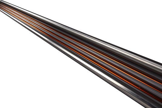
Continuous-access track busway
Uses an open slot along the run for compatible plug-in devices. Connection points can be repositioned at approved locations as equipment layouts change.
Best suited to: flexible overhead equipment distribution. Our What Is Track Busway? guide explains the parts, layouts, and USA TrackBusway system options.
Watch a T225 Track Busway Installation
See this continuous-access system take shape, from supports and joiners to the feed and plug-in tap-off units.
These are common arrangements, not an exhaustive list. Specialized systems include trolley busway and medium-voltage bus duct.
How an Electrical Busway System Works
A feed connects the electrical source to enclosed busbars. Joints connect sections into a route, and supports hold the assembly in place. In a plug-in system, compatible tap-off devices take power from the busbars to individual loads.
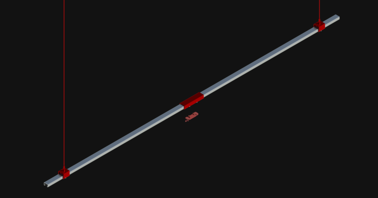
Conductors & housing
The busbars carry current. Insulation and the enclosure support and protect the conductors.
Joints & supports
Compatible joints maintain the electrical and mechanical connection between lengths; hangers or supports carry the assembly.
Feeds & tap-offs
Feeds supply the busway. Bus plugs or tap-offs supply equipment where the selected system permits connections.
When Does Busway Make Sense Instead of Cable and Conduit?
Busway can consolidate a distribution route into factory-built sections. Cable and conduit offer a familiar way to route individual circuits. The better fit depends on loads, space, installation conditions, and future changes.
Conduit + wire
A new connection may need field work.
Red dashed = possible new conduit work
Continuous-access busway
A compatible tap-off can serve B here.
Solid red = access to plug-in power overhead
Gray = former B position
Consider busway when
- Several loads share a common distribution route.
- Modular sections simplify installation or future expansion.
- Plug-in access would reduce rework when equipment moves.
- A backbone route calls for a suitable feeder busway system.
Consider cable and conduit when
- Circuits and equipment locations are expected to stay fixed.
- The route requires extensive custom field routing.
- The available busway does not suit the environment or required ratings.
- The complete installed-cost comparison favors conventional wiring.
Busway is not automatically cheaper. Compare equipment, installation labor, supports, protective devices, downtime, and the likely cost of future changes.
Where busway is used
Examples include manufacturing facilities, data centers, laboratories, commercial buildings, hospitals, and high-rise distribution. Backbone feeders and flexible equipment connections may use different busway types within the same facility.
Busway Ratings and Selection Considerations
A busway's name or appearance is not enough to select it. Match the actual product documentation to the electrical design and installation environment.
- Voltage, current, and conductors: confirm voltage, phase, ampere rating, neutral and grounding arrangements, and calculated load.
- Fault current and protection: coordinate busway short-circuit ratings with available fault current and protective devices. Device interrupting ratings and busway withstand ratings describe different duties.
- Route and environment: check clearances, supports, joints, voltage drop, enclosure ratings, and indoor or outdoor suitability.
- Connection method: confirm tap-off locations, compatible devices, and the protection required for each load.
Standards and product listings
UL 857 covers busway and associated fittings. NEC Article 368 addresses busway installations. Apply the code edition adopted for the project and the instructions for the listed product.
Ratings vary by system; a voltage or ampere limit for one Track Busway product is not a limit for the entire busway category. See USA TrackBusway's listing and code information for our systems.
Common Questions About Electrical Busway
Is busway the same as bus duct?
The terms commonly overlap. Read the specification to identify the system's intended use, access method, construction, and ratings rather than assuming those features from its name.
What is compact or sandwich busway?
These terms describe construction with closely arranged conductors in a compact enclosure. Construction style and tap-off access are separate characteristics; check whether the selected product is feeder or plug-in.
Can track busway replace a high-amperage feeder?
They serve different distribution needs. A replacement requires an electrical design that satisfies all loads, ratings, protection, and routing requirements. A lower-rated track run is not a direct substitute for a higher-rated backbone feeder.
Is every busway suitable outdoors?
No. Confirm the specific product's enclosure rating, environmental suitability, and installation instructions. An indoor system should not be assumed suitable for moisture, dust, or outdoor exposure.
Need Flexible Power Along an Overhead Run?
Learn how continuous-access Track Busway delivers power to equipment and how its components fit together.
