
225A Track Busway Power Feed Units

Specifications
| System | 225A Track Busway |
|---|---|
| Phase | 3 Phase + Neutral |
| Voltage | Up to 600V |
| Amperage | 225A |
| Pole Count | 4-Pole |
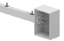
| Function | Brings building power into the busway run |
| Feed Options | Standard, IG, N2, N2IG |
| Used With | Matching 225A Track Busway lengths and conductor configuration |
See 225A Track Busway Power Feed Units in Action
Watch how this product installs, connects, or configures with the Track Busway system
For additional installation scenarios, configuration examples, and system overviews, visit the Track Busway Video Library →
USA TrackBusway
SKU: Catalogue # (SKU): EF225-4-600-N-S-S-NPM
How to Choose
Choose Standard for normal 3-phase + neutral layouts. Choose IG when isolated ground is required. Choose N2 for 200% neutral applications. Choose N2IG when both 200% neutral and isolated ground are required.
Couldn't load pickup availability
225A Track Busway power feed units connect facility power to USA Track Busway higher-capacity busway runs. For larger rows, equipment zones, phased expansions, and heavier industrial layouts, feed placement can be planned as part of a modular capacity strategy, allowing power to be introduced closer to the load or into separately fed sections as the layout grows.
Planning Feeds for Multiple 225A Runs?
For larger 225A layouts, feed placement may be coordinated with splitter-based planning, separately protected sections, or multiple downstream 225A Track Busway runs. Splitter Layout Planning can help show how a larger incoming feeder may be divided into protected downstream paths, with each feed, section, conductor configuration, and overcurrent protection scheme reviewed as part of the project electrical design.
What This Component Does
225A Track Busway power feed units bring building power from the source panel, switchgear, or distribution equipment into a 225A busway run. Each feed must match the selected busway conductor configuration: Standard, Isolated Ground, 200% Neutral, or 200% Neutral + Isolated Ground.
For larger layouts, the feed is not just an accessory. Feed placement is part of the electrical strategy. USA TrackBusway can support distributed feed planning where power is introduced closer to the load or into intentionally separated feed zones, subject to project drawings, overcurrent protection, conductor continuity, voltage drop, and code requirements.
Downloads – 225A Track Busway Power Feed Units
-
Download PDF Cut Sheet – 225A Track Busway Power Feed Units
-
Download Revit ZIP (.ZIP) – 225A Track Busway Power Feed Units
-
Download Revit Family (.RFA) – 225A Track Busway Power Feed Units
-
Download 3D Model (GLB) – 225A Track Busway Power Feed Units
-
Looking for more technical assets?

Conductor Configuration Note
225A / T225 conductor configurations can include Standard, Isolated Ground (IG), 200% Neutral (N2), and 200% Neutral + Isolated Ground (N2IG) where specified and supported. These are project-specific conductor options, not default features on every USA TrackBusway product.
Coordinate the selected busway length, power feed, tap-off units, voltage system, project drawings, load calculations, and electrical engineer requirements before ordering.
Review grounding and conductor configuration guidance.
-
Plan the Complete 225A Track Busway Run
A complete 225A Track Busway run typically includes:
- 225A Track Busway straight sections
- One or more coordinated power feed units
- Matching conductor configuration
- Electrical joiner kits
- Suspension hangers
- End caps
- 225A tap-off units
- Project layout drawing
- Electrical coordination with the source panel and overcurrent protection
-
When Multiple 225A Feed Points Make Sense
Multiple 225A feed points may make sense when a layout is large, phased, divided by equipment zones, or planned for future expansion. In those cases, the 225A Track Busway system can be designed with separately fed sections rather than relying on one feed location for the entire project.
For layouts involving multiple downstream 225A runs, protected sections, or larger incoming feeder coordination, see Splitter Layout Planning. Complimentary design drawings can also help plan feed placement, load distribution, sectioning, and future expansion requirements.
Multiple feeds require coordinated electrical design. Where more than one feed point is used, the layout must be reviewed for sectioning, overcurrent protection, conductor continuity, voltage drop, source coordination, load calculations, and applicable code requirements.
A 225A power feed unit brings building power from the source panel or distribution equipment into the Track Busway run. It must match the busway conductor configuration and project electrical requirements.
Choose Standard for typical 3-phase + neutral layouts. Choose IG where isolated ground is required. Choose N2 where 200% neutral is required. Choose N2IG when both 200% neutral and isolated ground are required.
Feed placement should be coordinated with the source panel, system layout, voltage drop, tap-off density, access, project drawings, and future expansion plans. For larger 225A layouts, USA TrackBusway can help review whether the feed should be located near the beginning of the run, closer to a load zone, or within an intentionally separated section.
Yes. Multiple feeds can be used where the layout is intentionally divided into separately fed sections. This can be useful for larger layouts, phased expansions, or equipment zones with different power requirements. Feed strategy must be coordinated with the project electrical design, overcurrent protection, conductor continuity, voltage drop, and source-panel requirements.
No. Multiple feeds should not be presented as casually paralleling one continuous energized run. Where multiple feed points are used, the layout should be intentionally divided into separately fed sections and coordinated with the project electrical design.
Yes. USA TrackBusway can review project drawings and help identify feed placement, feed type, conductor configuration, and related components for a complete 225A Track Busway layout.
Splitter-based layouts may use 225A feed units as part of coordinated downstream paths, separately protected sections, or multiple 225A Track Busway runs. A splitter does not increase the rating of a single 225A run. It helps organize project-level distribution where the upstream source, overcurrent protection, conductor configuration, load calculations, and project electrical design support the layout.
Yes. Dedicated Ground / DG is available as a project-specific configuration where specified and supported. In a dedicated-ground configuration, an added internal grounding conductor is bonded to the equipment-grounding path and housing/enclosure ground. This is different from Isolated Ground / IG, where the insulated grounding path is maintained separately through compatible components and field wiring.
Isolated-ground receptacle options are available when specified on supported factory-assembled tap-off configurations. USA TrackBusway does not sell loose standalone receptacles.
200% neutral, also searched as 200 percent neutral, is available only as a project-specific 225A / T225 conductor configuration where supported. It must be coordinated with drawings, load calculations, voltage system, and electrical engineer requirements.
200% Neutral + Isolated Ground can be specified as N2IG where supported by the selected 225A / T225 configuration. Coordinate busway lengths, feed units, tap-off units, drawings, and electrical design before ordering.


