
40A Track Busway system
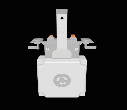
T40 208V-1Ph PowerDrop Cord


Specifications
| Phase | Single-Phase |
|---|---|
| Voltage | 208 |
| Amperage | 15A / 20A / 30A |
| Pole Count | 2 |
| NEMA | L6-15, L6-20, 6-20R, L6-30 |
The 208V PowerDrop Cord delivers single-phase branch power from a compatible 40A USA TrackBusway system through a 2-pole breaker and flexible drop cord.
Measure the cord route from the overhead run to the equipment connection, including any horizontal reach. Place the drop where the connector remains accessible while keeping the cord clear of aisles and equipment service panels.
Build your tap-off
Choose each option below to confirm your tap-off and price, then review the downloads and specifications for your build.
Catalogue number MD40-3-208-CB20-DC-XX-ST-G
Couldn't load pickup availability
Documents for your selected tap-off
Product family cut sheets and Revit resources. Check that the document or model covers your selected configuration.
ETL Listed to UL 857 Busway Standards
For 40A Track Busway system models and configurations covered by the listing.
See T40 208V-1Ph PowerDrop Cord in Action
T40 208V-1Ph PowerDrop Cord Wiring Diagrams
Standard Wiring: A and B
The illustrated single-deck connection uses phases A and B from a 208Y/120V supply. The standard version also accesses A and B on the lower deck of a double-deck three-phase 40A system. Both phases feed the 2-pole breaker; this 208V branch does not use neutral.

Double-deck whip wiring (B/C example)
The diagram shows the B/C pickup. The same whip option also supports A/C: upper-deck C pairs with either lower-deck phase. Both phase pairs supply 208V line-to-line on a 208Y/120V run and use a two-pole breaker.

Part of the 40A Track Busway System
This breakered PowerDrop connects a compatible 40A Track Busway run to equipment below through a flexible cord. Build the supply path with 40A track busway lengths and the appropriate power feed.
Match the selected tap's voltage, phase connection and breaker rating to the supply and equipment. Use the Track Busway system design guide to plan the complete layout.


Planning equipment additions along a busway run
Map current equipment and likely future stations before finalizing tap-off positions. Record which loads will operate together and where machines need service access; an available connection position alone does not establish spare electrical capacity.
Keep a schedule of installed tap-off catalogue numbers and the equipment they serve. When a workstation changes, review its supply and connection needs before reusing an existing assembly.
 Overhead Power DistributionExplore Applications & Projects
You may also like



- Choosing a selection results in a full page refresh.
- Opens in a new window.
